Couldnt really sleep last night as i have been getting excited about working on the savage again!
I am really determined to get this idea sorted.... everytime i make a little progress, i think of another problem that gets in the way... So here is where i am at. Please chime in.
OK SO FIRSTLY, something need to be taken into consideration.
The centre diff can not be raised any higher or drive shafts will hit on componants.
i worked out a way of possibly fitting the brake linkages and servo without getting in the way of my motor and pinion.
Here is the method i could use to mount it.
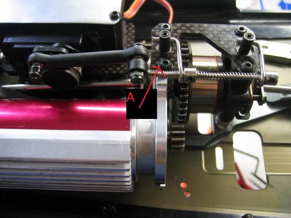
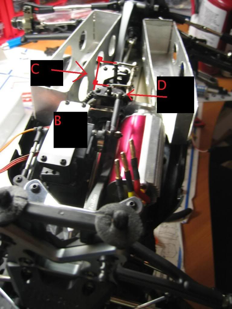
At point B, i would obviously have the servo mounted standing and attached to the side of the TVP parallel to the motor. See image below for terrible diagram.
Instead of having the brake linkage assembly where it currently sits in the above images... i would have it on the opposite side (POINT C)... this would allow the motor to sit above point D.
But it looks like i will not be able to use my existing centre diff mounts if i cannot fit the hyper st carbon pro carbon diff plate linked below
http://cgi.ebay.co.u...IT#ht_500wt_997
Which means i would most likely go for the full centre diff and full brake assembly kit from an ST Pro linked below
http://cgi.ebay.co.u...c1#ht_500wt_997
It should hopefully be able to handle the brushless power without flexing i hope. I am just unsure whether or not the pinion on the motor will be able to reach the spur... If this is a problem, maybe a larger 52t spur will help ?
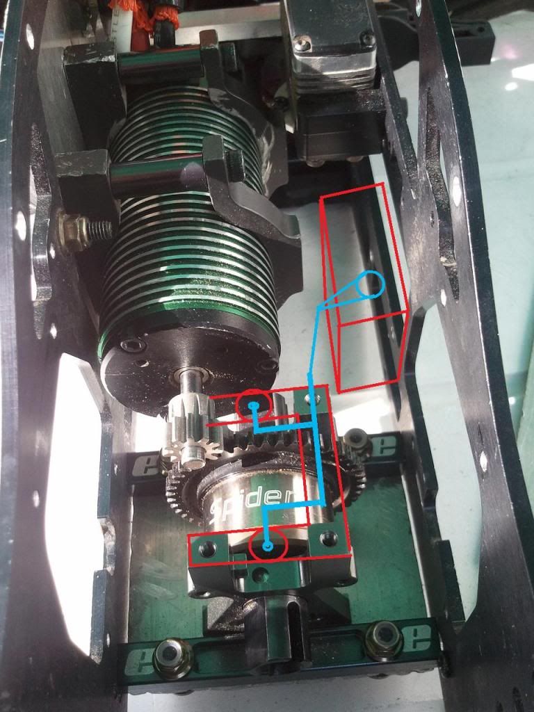
the reason i cannot use my existing mounts unless i do not necessarily have to mount the carbon top plate across all 4 posts as the motor pinion will not make contact with the spur. I had to chop one of the posts of so there was contact. As you can see in the pic below, the posts where the diff top plate attach too are quite tall. I had to cut the post as low as the screw hole where the pads attach to (hopefully you get one i mean) you should be able to notice this in the images below where the motor shaft sits in line with the diff mount posts...

SO THEN JUST AS I JUST ABOUT THOUGHT I HAD CRACKED IT... I RAN INTO ANOTHER PROBLEM!
Look at this image below which shows why one post has to be chopped for the pinion to meet the spur.
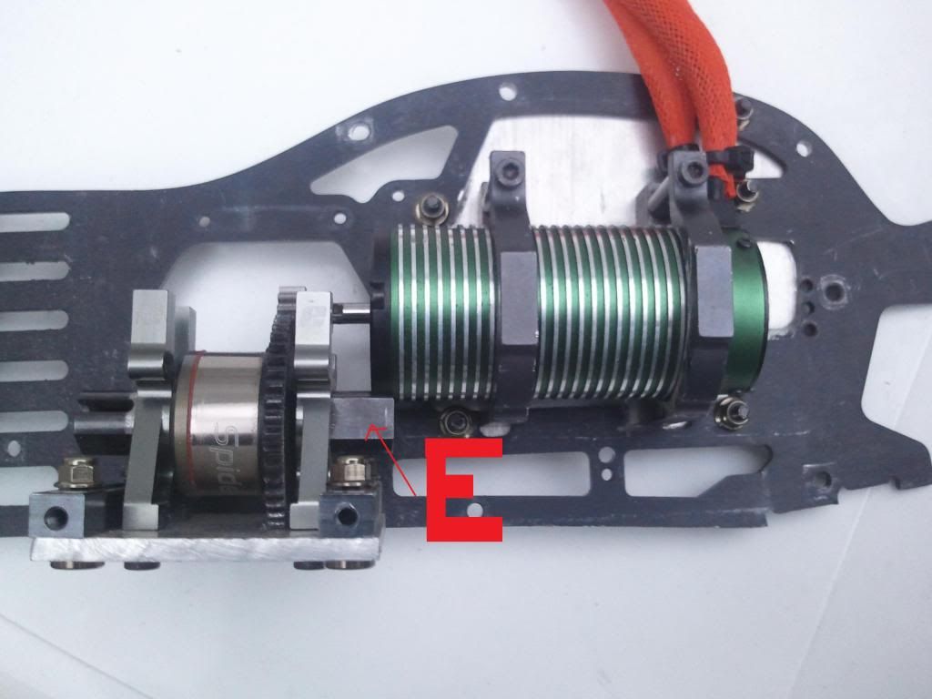
So another problem i noticed i would have...
If the brake discs were sitting on the diff outdrives at "E" in the above pic... THEY WOULD MOST CERTAINLY HIT THE CROSS BRACE JUST BELOW!
By how much... i dont know until i try... Maybe i could grind a little out but, if i do too much, it could make things weak...
YES LINC
I did have an idea to make a whole new centre diff mount plate, and move the centre diff all the way to one side and then mount the motor as low as possible in the chassis so the pinion meshs to the side of the spur rather than the top.
But this would cuase many problems...
I would need 2 new drive shafts as the distances would be increased slightly.
The motor would mount so low that the drive shaft would hit the motor clamps
The motor would mount so low that the steering servo horn would hit the motor (only just about clears it right now!)
The chassis would need a lot of work... i would need to mount another plate for the brake servo to mount too...
Sorry for the bad drawings, but i tried to make it as easy to understand and simple to see as possible
ALSO LINC I NOTICED YOU ARE SELLING AN ESC???
Do you think i could use it for my applications?
Does it have brake function?