

Use 12v fans for your ESC/motor... |

|

|
(#1)
|
|
RC-Monster Admin
Offline
Posts: 14,609
Join Date: Nov 2005
Location: Des Moines, IA
|
Use 12v fans for your ESC/motor... -
01.20.2007, 05:36 AM
Even though I personally don't like to use fans, I can see their usage for those who push things too far (you know who you are!). But it can be difficult to find 5v-6v fans. But 12v fans of all sizes are pretty much at any computer store.
So, I thought I'd put together a little how-to for wiring up a 12v regulator so we can use 12v fans instead. Parts list:
Pictures are worth a 1,000 words so: 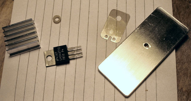 These are the parts I used. You can see the regulator mounting kit. Just a mica (I think) insulator and a flanged plastic washer to keep the regulator electrically insulated from the heatsink, yet thermally coupled. The aluminum heatsink is 1" wide x 1/8" thick x 2.25" long. A hole was drilled and tapped for a 3mm screw roughly in the middle. I also am using a piece of a heatsink from my spare parts bin. 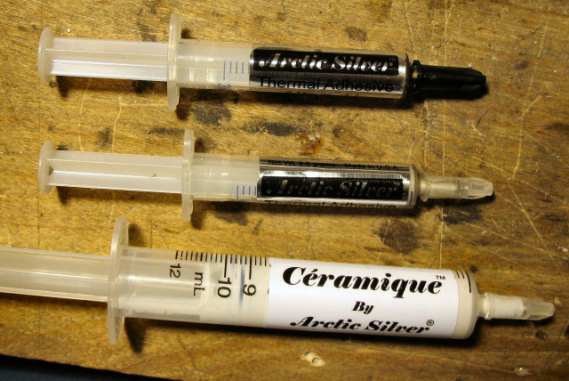 The Artic Silver products I'm using. The "Ceramique" is a thick type of thermal compound (not adhesive) for the regulator. The thermal epoxy is to hold the finned heatsink to the Al slab. 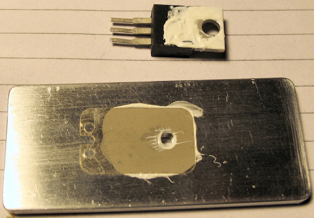 You can see I put some compound on one side of the insulator and pressed it where it needs to go, and put some compound on the regulator. It's OK if you use too much as any excess will squish out (but can be messy). 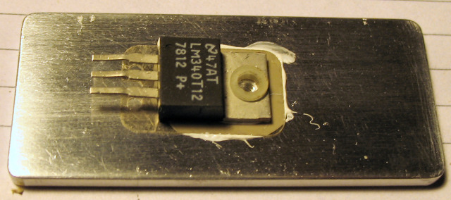 I put the regulator in place and put the washer in the regulator hole so the flanged edge lays on top of the tab. 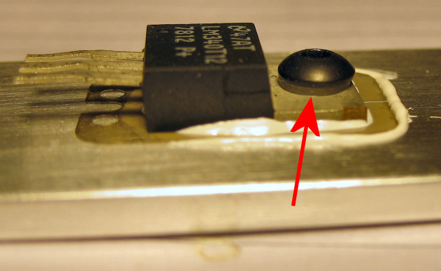 I used a 3M thread x 6mm long screw to secure it to the heatsink slab. Note the flanged washer position. 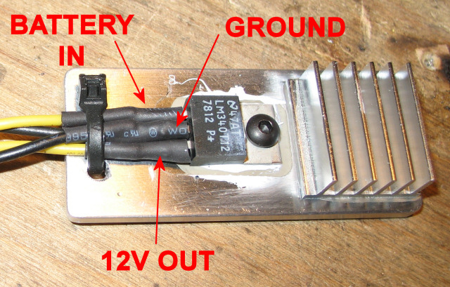 I thermal epoxied the finned heatsink on the end of the slab. Then I soldered the wires on the regulator. The center pin is ground. Make sure two ground wires go here - one from the batts and one to the load. Just strip the ends, twist the wire together, and solder it to the center pin. The leftmost pin is the input from the batteries. The rightmost pin is the 12v output. Then put some heatshrink over the connections. Also note the holes drilled on the side of the wire. The zip tie is a crude strain relief. 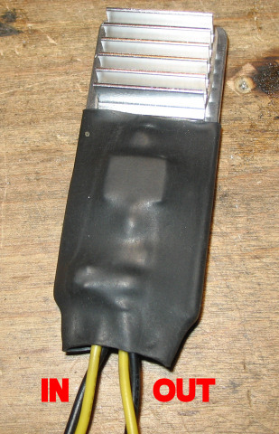 The finished part with some heatshrink over the whole thing. Make sure to keep at least half the heatsink uncovered, but make sure the regulator itself IS covered. Twist one ground wire (doesn't matter which one) with the input wire to go to your batteries. Twist the other ground wire with the output wire to go to your fan(s). That's it! Now a little math. This is a linear regulator, so it will heat up. The amount of heat it produces is determined by how many cells you are using and the current drawn by the fan(s). Wasted power (as heat) = ( battery_V - 12v ) * fan_current. As you can see; high battery voltage and/or high current is going to create more heat. As a test, I used a battery pack measured at almost 20v. I found a 12v 40mm fan that draws 0.07A, which is fairly typical. When I hooked up the regulator, the temerature went up to about 80 degrees F. This equates to 0.56watts wasted on the regulator: (20v-12v)*0.07. I also found a high output large crossflow fan that requires 0.250A. This is wayyy bigger than needed to cool an ESC, but even so, the temperature only got to 108 degrees F. Wasted power was 2watts: (20v-12v)*0.25. So, this setup will easily power a typcial 12v 40mm-60mm fan and barely get warm using up to 5s or 16ish cells. It will power 2 of these and get a little warm. Three, and the regulator starts getting toasty. If you use 4s/12 cells, the regulator will heat up less. Hope this helps someone... |
  |

|
|
|
|
|
(#2)
|
|
RC-Monster Aluminum
Offline
Posts: 702
Join Date: Feb 2005
Location: n.c.
|
01.20.2007, 09:01 AM
nice write up!
phil Slash 4x4 163mph drc rail 150 mph phildogg6@yahoo.com https://www.youtube.com/channel/UC1g...MR6SqQkehkevwA my youtube channel |
 |
|
|
|
|
|
(#3)
|
|
Always Willing to Obtain More Knowledge
Offline
Posts: 1,482
Join Date: Oct 2006
Location: Chicago
|
01.20.2007, 10:13 AM
Very helpful to me in the future
|
|
|
|
|
|
|
|
(#4)
|
|
RC-Monster Dual Brushless
Offline
Posts: 3,493
Join Date: Feb 2005
Location: Canada
|
01.20.2007, 11:02 AM
Nicely done Brian!
Losi 8ight e MMM / Neu 1512 2.5d/f Thunderpower 5s 5000 |
|
|
|
|
|
|
|
(#5)
|
|
RC-Monster Admin
Offline
Posts: 10,480
Join Date: Feb 2005
|
01.20.2007, 11:04 AM
Yeah, Nice write up Brian.
You could use an aluminum chassis as a heatsink too.. |
|
|
|
|
|
|
|
(#6)
|
|
RC-Monster Admin
Offline
Posts: 14,609
Join Date: Nov 2005
Location: Des Moines, IA
|
01.20.2007, 11:28 AM
Thanks guys.
Serum: I was shooting for a BEC-like package, but yes, using the chassis as the heatsink would be fine, as long as it was aluminum. It's too bad I didn't need a -12v regulator as I seem to have about 40 of those for some reason. :032: |
|
|
|
|
|
|
|
(#7)
|
|
Guest
Posts: n/a
|
01.20.2007, 11:44 AM
I used a 24V fan instead, that was on my 9920. So that even on maximum cell count the fan would be comfortable. Was about a 3" dia. fan though. Came from a photocopier, nearly cut my finger off taking it out. Saves any extra voltage regulators etc...
|
|
|
|
|
|
|
|
(#8)
|
|
RC-Monster Carbon Fiber
Offline
Posts: 252
Join Date: Aug 2006
Location: Estonia, Tallinn
|
01.20.2007, 01:53 PM
I have question, How much Fans reduce aprox. runtime?
Fan produce 1,2W of power so on 5V its 240mA. So how much it takes in hour? |
|
|
|
|
|
|
|
(#9)
|
|
TEAM FUSION
Offline
Posts: 2,041
Join Date: Jul 2006
Location: Iowa... Hawkeye country
|
01.20.2007, 02:48 PM
Here's some fun wasting a few minutes, but useful I think :)
A typical small fan @ 70mah as BG tested would suck 70ma in one hour. So let's say an average run time is 20 minutes for a LIPO/BL creation.... that's a whopping 23milliamp worth of battery wasted, which equates to about 6 seconds of runtime for a 1/10 car using (conveniently) 230mah/ minute. My 1/8 buggy gets @ 20 min on 6000mah... not unusual. That's 300mah per minute. Let's say I have lots of cooling: Two 40mm 125mah fans = 250mah draw= 83ma used in 20 min. = 16.6 seconds of runtime. That's not a lot, (1.3% reduction in runtime) but it does equal one full lap (out of 72 thoeretical laps) on a small track... but's it's worth keeping everything cool. :) And remember a 70mah fan would only put a 4-5 second dent in the runtime, like 0.3% reduction.... |
|
|
|
|
|
|
|
(#10)
|
|
RC-Monster Admin
Offline
Posts: 10,480
Join Date: Feb 2005
|
01.20.2007, 02:56 PM
240mAh (on 5V)
on 12V that would be 100mAh On 24V it would be 50 mAh |
|
|
|
|
|
|
|
(#11)
|
|
RC-Monster Admin
Offline
Posts: 10,480
Join Date: Feb 2005
|
01.20.2007, 03:03 PM
So if you put a 12V 250mAh fan and use it on 5S lipo with BrianG's 'converter' and use it for 20 minutes, the energy it takes from the 5S will be 54mAh
(even less than Glass calculated, he forgot the higher voltage of the batteries) i am neglecting the losses of the 7912 |
|
|
|
|
|
|
|
(#12)
|
|
TEAM FUSION
Offline
Posts: 2,041
Join Date: Jul 2006
Location: Iowa... Hawkeye country
|
01.20.2007, 03:26 PM
I didn't forget ;)
I was trying to give a basic example to answer the question about how much juice/runtime a fan uses. I wasn't even thinking of BG's converter... and I was thinking 4s too. Assuming the fan pulls x current, without regard to the input voltage from the battery. Higher voltage would result in higher amp draw from the fan anyway, which changes the #'s. So maybe we can go back and figure in the losses from the converter and the draw from a given fan @ 12volts... add them and see what the total effect is. |
|
|
|
|
|
|
|
(#13)
|
|
RC-Monster Admin
Offline
Posts: 14,609
Join Date: Nov 2005
Location: Des Moines, IA
|
01.20.2007, 06:33 PM
Yeah, I forgot to figure in the effect in the runtime.
Using a fan off a 5 or 6v switching UBEC is actually more efficient that using a 12v regulator to power the 12v fan even thought the 5v one draws more current since the 12v regulator is linear. Just for reference, most of the small, moderate airflow 12v fans draw between 0.05 and 0.08A each. As you get bigger and/or get ones with more airflow, current can get up to 0.75A for extreme cooling. But the smaller 40mm fans are fine... :) At any rate, unless you're running lots of fans (3+), the effect on runtime is minimal and can be measured in seconds. This is just a cheap and dirty way to be able to use very commonplace 12v fans without overpowering them with full battery voltage. |
|
|
|
|
|
|
|
(#14)
|
|
Guest
Posts: n/a
|
01.21.2007, 01:45 AM
If you really wanna get anal about it, the motor and electronics are more efficient when cooler. LOL, My money says it'd be a wash, or you may even gain runtime if your cooling vs fan amperage is right.
|
|
|
|
 |
«
Previous Thread
|
Next Thread
»
| Currently Active Users Viewing This Thread: 1 (0 members and 1 guests) | |
 Linear Mode

|
|

Powered by vBulletin® Version 3.8.11
Copyright ©2000 - 2026, vBulletin Solutions Inc.
vBulletin Skin developed by: vBStyles.com
Copyright ©2000 - 2026, vBulletin Solutions Inc.
vBulletin Skin developed by: vBStyles.com