

|
|
PC Power Supply Mod. |

|

|
(#1)
|
|
RC-Monster Carbon Fiber
Offline
Posts: 119
Join Date: Mar 2010
|
PC Power Supply Mod. -
04.15.2010, 05:33 PM
Alrighty!
So reading through Brian's write up along with several others coversions for charging duty I decided it was definately the way to go. So I order a solid Corsair 400w single rail power supply capable of supplying 30A on it's 12v rail. Fast forward, PS is open torn down here in front of me. I measured the 12v output and looks like about 12.17'ish solid. So should be good there. So looking at making a few wiring mods to support my Hyperion 720i for charging duty. I'm planning on going to 12AWG DC out so looking at the board to find the taps and I see what says 12v1+12V2... WTF  That said, I've got 2 sets of 4x 18AWG wires tapped into 12v1 on the board and a set of 3x 16AWG 4yellow with black stripes that I think are on 12v1 though I won't be able to tell until I get to the house and pull the board from the case to see. Thoughts? I'll assume this doesn't have 2x 12v rails, no? I "believe" the yellow with blacks (had corresponding blacks with white) were from the PCIE 6 pin video card cable. Thoughts? |
|
|

|
|
|
|
|
(#2)
|
|
RC-Monster Admin
Offline
Posts: 14,609
Join Date: Nov 2005
Location: Des Moines, IA
|
04.15.2010, 05:41 PM
Yeah, it sounds like it has two 12v rails.
Some people may say to just tie them together to get the sum of both rail current ratings. However, I've worked on a PS with dual 12v rails and the internal heatsink got quite hot when they were tied together. Each PS is different so you may be perfectly fine doing this, but I would run a test first; Temporarily hook the 12v rails together, and then hook the paralleled 12v wires to the charger, and charge a pack. Monitor the 12v voltage and current to see how much the voltage sags at whatever current the charger is pulling. If the PS gets hot (and will happen withing a minute or two if it will) then there is an issue and each set should be used independently. If the PS stays cool, then you are fine with paralleling both 12v rails. But be warned; certain components in the PS are running at dangerous voltages. Sometimes, even a heatsink can be floating at high voltage, so BE CAREFUL!!!! |
  |
|
|
|
|
|
(#3)
|
|
RC-Monster Carbon Fiber
Offline
Posts: 119
Join Date: Mar 2010
|
04.15.2010, 05:44 PM
Brian,
Here's the power supply... http://www.newegg.com/Product/Produc...82E16817139008 Clearly states "powerful single rail".... Let me get you a picture for a visual. |
|
|
|
|
|
|
|
(#4)
|
|
RC-Monster Admin
Offline
Posts: 14,609
Join Date: Nov 2005
Location: Des Moines, IA
|
04.15.2010, 05:55 PM
Hmm, it does say that in the specs and the reviews. Taking the board out will be the best way to tell then. I don't know why they would use different appearing wires if they go to the same electrical point - maybe they ran out of solid yellow?
 I looked at the pics on Newegg and I didn't see a sense wire on the mobo connector (would be a smaller gauge yellow wire that is tied to the main yellow wire on the mobo connector), but the pic isn't the best, so I'm not sure. There could also be a pot you can tweak in there as well. BTW: Even though the PS is off/unplugged, there may be some caps with high voltage on them - so again, be careful. Don't mean to be repetitive, but don;t want to read about you in the obits... |
|
|
|
|
|
|
|
(#5)
|
|
RC-Monster Carbon Fiber
Offline
Posts: 119
Join Date: Mar 2010
|
04.15.2010, 05:59 PM
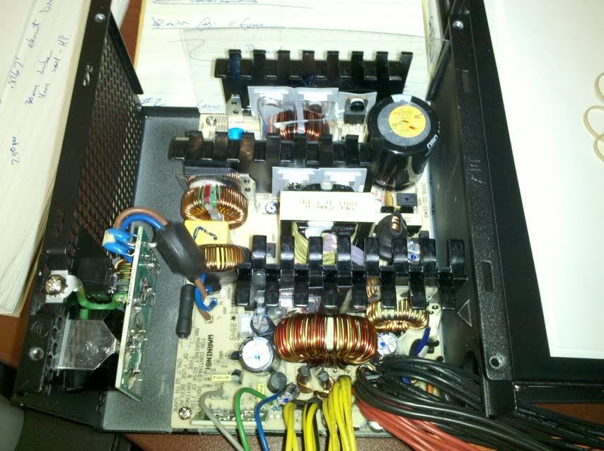
Here's the pic (sorry Droid pic).
|
|
|
|
|
|
|
|
(#6)
|
|
RC-Monster Carbon Fiber
Offline
Posts: 119
Join Date: Mar 2010
|
04.15.2010, 06:01 PM
NP on the warning. I've been working on 480v 1250A service on our new equipment here.
As I tell people "hands in pockets" when they are near the panels.....  Like I said, I need to pull the board to check. And you are right, the only sense wires I seem to have with this supply are on the +3.3v stuff. |
|
|
|
|
|
|
|
(#7)
|
|
RC-Monster Admin
Offline
Posts: 14,609
Join Date: Nov 2005
Location: Des Moines, IA
|
04.15.2010, 06:02 PM
Hmm, don't see any pots to adjust. If they are there, they are generally pretty close to the FETs/coils. I think I might see one between the primary transformer and coil (roughly in the middle), but if it is, it is probably not to tweak the voltage.
|
|
|
|
|
|
|
|
(#8)
|
|
RC-Monster Carbon Fiber
Offline
Posts: 119
Join Date: Mar 2010
|
04.15.2010, 06:11 PM
I'm not overly concerned about upping the voltage as the charger will just pull more current.
Being the voltage is 12.17v, provided there isn't a lot of line drop, it should be ok. Seeing as I'm looking to charge at 2c for my 4200mah setup your talking ~10A so with 30A main feed, I should have some headroom. I'm more concerned about the board listing 12v1 and 12v2 nearest the power wires. In the bottom of the image, you can see the yellow/blacks 3pair and the 2pair under those (to the left). The 12v2 is listed right there. 12v1 is listed nearest the 2x 4pairs above (to the right). |
|
|
|
|
|
|
|
(#9)
|
|
RC-Monster Carbon Fiber
Offline
Posts: 119
Join Date: Mar 2010
|
04.15.2010, 06:13 PM
Going to need to pull the board to see/tell anything huh?
Also, as a neat aside... Looks like they are using this PCB for the 250-5000w power supplies. Makes me wonder if the 12v2 is a listing for the more powerful board options???? Just a though. I also don't see any POT's in here. Appears voltage is fixed. <-----(heading to the house to pull board).... Stay tuned. |
|
|
|
|
|
|
|
(#10)
|
|
RC-Monster Admin
Offline
Posts: 14,609
Join Date: Nov 2005
Location: Des Moines, IA
|
04.15.2010, 06:16 PM
Actually, upping the voltage will make the charger pull less current. Chargers have built-in switching supplies that turn 12v input into whatever output needed to charge the battery. So, for a given power output, higher PS voltage = less PS current required.
If you pull the board out, just follow the traces. It should be pretty obvious where they go since they are rather large. The v1/v2 marking could very well be for larger supplies. Hard to tell. |
|
|
|
|
|
|
|
(#11)
|
|
RC-Monster Carbon Fiber
Offline
Posts: 119
Join Date: Mar 2010
|
04.15.2010, 07:47 PM
Alright, here's the bottom of the pcb....
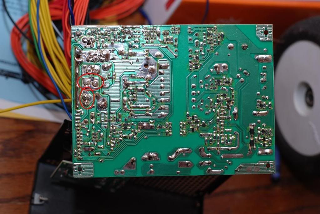 12v marked with red circles. |
|
|
|
|
|
|
|
(#12)
|
|
RC-Monster Carbon Fiber
Offline
Posts: 119
Join Date: Mar 2010
|
04.15.2010, 07:48 PM
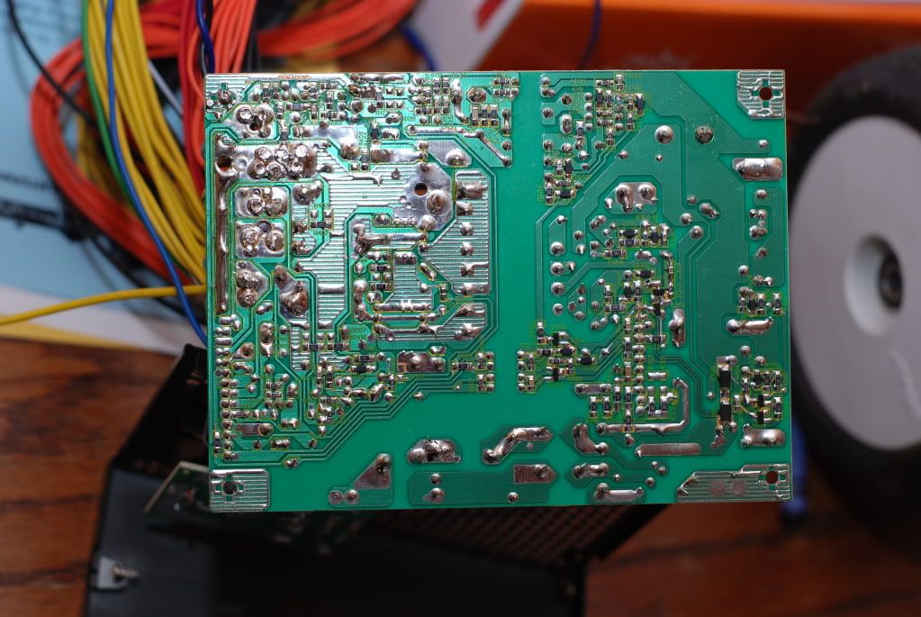
Image without circles.
|
|
|
|
|
|
|
|
(#13)
|
|
RC-Monster Carbon Fiber
Offline
Posts: 119
Join Date: Mar 2010
|
04.15.2010, 07:58 PM
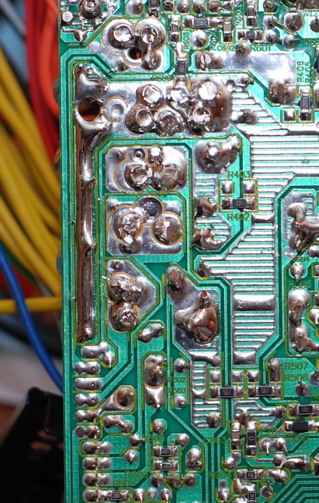
Close up of area...
|
|
|
|
|
|
|
|
(#14)
|
|
RC-Monster Carbon Fiber
Offline
Posts: 119
Join Date: Mar 2010
|
04.15.2010, 09:55 PM
Did some more research...
Appears this IS a single rail power supply or at least, they are pulling power from a single rail. The actually supply puts out better than 450watts true power and closer to almost 500W before it shuts down. Not bad for $50... Review. http://www.hardwaresecrets.com/article/750/1 Still doesn't explain the single rail design but still has 12v1 and 12v2 which they tested independantly. How do I combine this? Just jumper the pads and wire them together??? |
|
|
|
|
|
|
|
(#15)
|
|
RC-Monster Admin
Offline
Posts: 14,609
Join Date: Nov 2005
Location: Des Moines, IA
|
04.15.2010, 10:03 PM
OK, those two 12v areas probably have large coils going to another area. Circle the area where those coils go if you could. I'm thinking both those 12v lines come from the same output, but use seperate coils to avoid using one large coil,
|
|
|
|
 |
«
Previous Thread
|
Next Thread
»
| Currently Active Users Viewing This Thread: 1 (0 members and 1 guests) | |

 Hybrid Mode
|
|

Powered by vBulletin® Version 3.8.11
Copyright ©2000 - 2026, vBulletin Solutions Inc.
vBulletin Skin developed by: vBStyles.com
Copyright ©2000 - 2026, vBulletin Solutions Inc.
vBulletin Skin developed by: vBStyles.com