RC-Monster Forums  

Go Back   RC-Monster Forums > Support Forums > General Electric

Reply
 
Thread Tools Rating: Thread Rating: 4 votes, 4.00 average. Display Modes
Trolling Motor powered by lithium ion 18650's?
Old
  (#1)
sikeston34m
RC-Monster Brushless
 
sikeston34m's Avatar
 
Offline
Posts: 2,085
Join Date: Sep 2007
Trolling Motor powered by lithium ion 18650's? - 12.19.2010, 11:40 PM

Hi Guys,

I am an avid fisherman and love the outdoors.

I've replaced the trolling motor batteries on my boat so many times, it's getting old.

A regular trolling motor battery will only last about 2 years. It's all I can squeeze out of them.

The last replacement, I opted to go with 2 - 6 volt golf cart batteries. They are supposed to be good for 5 years. Well, they have lived for 3 years so far, but I can tell they are already getting tired.

This quest includes building a great performing lithium ion setup that will outlive anything lead acid has to offer.

The pack itself is going to be constructed from New lithium ion 18650 cells. 180 of them to be exact.

180 Sanyo 2200mah 18650 cells, working together in a 6S30P configuration.

This will make for 66ah at 25.2 volts fresh off the charger. For comparison purposes, this will be equal to 130ah+ at the operating voltage.

Check this out. Aren't they pretty?


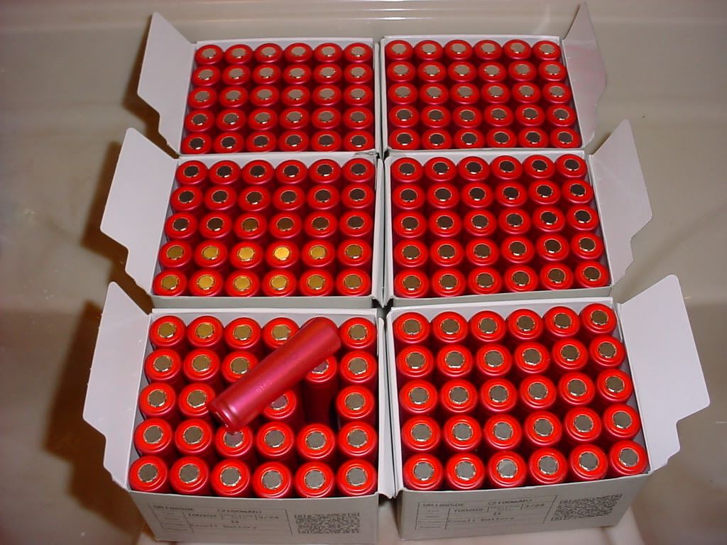
Now I bet you're wondering. 25.2 volts? That's gonna fry that trolling motor.

If the pack were directly hooked up, then yes. The magic genie smoke would come out.

But.........that's not what we're going to do.

We're going to use 5 DC to DC Vicor voltage converters that were recently acquired.

Input voltage range is: 18vdc to 36vdc Output voltage: 13.8vdc @ 200 watts each


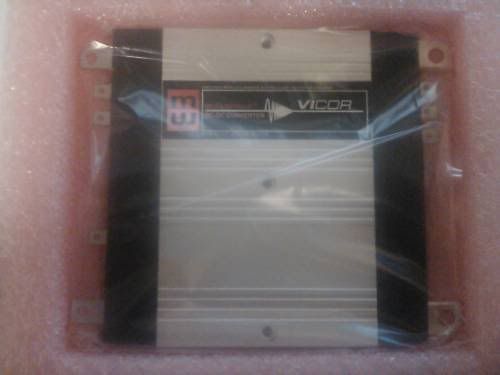
A couple of things I like about these converters are:

At 200 watts each, they will be paralleled for 1000 watts of total output. They will handle the load, since at maximum thrust, (55 ft lbs) the motor's output will be around 700 watts.

80% to 90% efficiency. I'm hoping to reach up toward the 90% mark, hence the total wattage headroom.

The converter will output a constant 13.8 volts. NO voltage sag. In other words, the charge will be just as fresh at the end, as it was at the beginning of the discharge cycle.

This should be a big improvement over the performance of lead acid since it's voltage sags quite a bit under the load.

One problem I have is:

How do I build this pack? I need 6 individual "Bricks" of 30 cells each.

What's the best way to go about building this?

It needs to be tough and somewhat waterproof.

Any suggestions guys?

Last edited by sikeston34m; 12.19.2010 at 11:45 PM.
   
Reply With Quote
Old
  (#2)
lincpimp
Check out my huge box!
 
lincpimp's Avatar
 
Offline
Posts: 11,935
Join Date: Aug 2007
Location: Slidell, LA
12.20.2010, 12:05 AM

Well, I would take a copper plate, draw a grid pattern with the lines spaced the diameter of the cells. Punch 1/4" or so holes where the lines intersect and solder the cells thru those holes. Wrap the packs of 30 cells in something that can be removed, such as large shrink, then place them in a waterproof box of some sort that has padding (closed cell firm foam?) on all sides and between each pack. Wire the packs in series with large gauge wire and add a balancing tap for testing purposes.

How much did those cells cost and where did you get them from?
   
Reply With Quote
Old
  (#3)
sikeston34m
RC-Monster Brushless
 
sikeston34m's Avatar
 
Offline
Posts: 2,085
Join Date: Sep 2007
12.20.2010, 12:15 AM

Quote:
Originally Posted by lincpimp View Post
Well, I would take a copper plate, draw a grid pattern with the lines spaced the diameter of the cells. Punch 1/4" or so holes where the lines intersect and solder the cells thru those holes. Wrap the packs of 30 cells in something that can be removed, such as large shrink, then place them in a waterproof box of some sort that has padding (closed cell firm foam?) on all sides and between each pack. Wire the packs in series with large gauge wire and add a balancing tap for testing purposes.

How much did those cells cost and where did you get them from?
This has been what I've been thinking about doing. My first thoughts were solder to copper plate. But then I thought.........

By doing it this way, it's going to be pretty hard to disassemble should the need arise.

Today, I took an old 18650 cell and soldered a galvanized screw to it. It's a counter sunk type machine screw.

What if I soldered one to each end of every cell. Then installed all the cells to the plate with lock washers and nuts?

This would make wiring hookups very easy and also make the pack easy to take apart. If the need were to arise.

On the copper plate, I've noticed that stuff is pretty spendy. I wonder if 1/8" aluminum plate would work? Afterall, aluminum is pretty conductive and it is used in the aerial cable that feeds our home. Would resistence be a factor if 1/8" aluminum plate were used?

Foam padding. A good idea!

I'm thinking of building an aluminum box to house the pack and the converters. I can caulk it up to make it resist water, plus it will be a natural heat sink.

This would also serve as a nice power station to use with an AC inverter.

I lucked out on the cells. You're looking at $150 bucks worth of cells plus shipping. It was a liquidation sale. I have tested samples. They do go full capacity.
   
Reply With Quote
Old
  (#4)
johnrobholmes
RC-Monster Aluminum
 
johnrobholmes's Avatar
 
Offline
Posts: 905
Join Date: Aug 2007
12.20.2010, 11:40 AM

Why not build the pack for the proper voltage in the first place? Is there some reason that you cannot do this? 3s would work with the trolling motor just fine, and you would have a higher system efficiency without the use of the DC converters. There won't be much sag to the pack anyway. Do you have a low voltage monitor on the pack planned as well?

No matter what you will be looking at a massive pack construction task. The cell body needs to be supported while keeping the connections flexible. I would suggest building smaller parallel chunks of cells that you can gang together in the case that pack work needs to be done.


Soldering will work, it is really the only choice you have. I would probably get some threaded copper bits and solder them on so that bolt on ring terminals could be used for cell interconnects. I like your idea of doing it the other way with the screw on the cell. Just don't support the cell by these.


---JRH---

Last edited by johnrobholmes; 12.20.2010 at 11:42 AM.
   
Reply With Quote
Old
  (#5)
J57ltr
RC-Monster Aluminum
 
Offline
Posts: 610
Join Date: Feb 2009
Location: Tomball/ Houston Tx.
12.20.2010, 08:05 PM

I am not sure why you would really want to use the DC-Dc converters. Why not just run 4s45p and be done with it, At that point you have a 99ah 14.4V battery. Adding the converters in there is going to make your system less efficient. What kind of BMS are you going to run?


The Warnings & Cautions discussed in this manual cant cover all possible conditions/situations. It must be understood that common sense and caution are factors which cant be built into this product.
   
Reply With Quote
Old
  (#6)
lincpimp
Check out my huge box!
 
lincpimp's Avatar
 
Offline
Posts: 11,935
Join Date: Aug 2007
Location: Slidell, LA
12.20.2010, 08:30 PM

Seems like he is using the dc to dc convertor to get a constant voltage thru the entire discharge cycle. I do agree that it adds complexity and has potential to lower effecientcy. Not sure if the lower load that the 6s pack will see may help cells such as this handle load better thus extending their lifespan and cuasing less voltgae drop under load. Might be as or more effecient than just running lower voltage. These are 2c cells, keep that in mind.
   
Reply With Quote
Old
  (#7)
sikeston34m
RC-Monster Brushless
 
sikeston34m's Avatar
 
Offline
Posts: 2,085
Join Date: Sep 2007
12.20.2010, 09:34 PM

Some good questions and good observations.

First off, I would like to say that most things that run on 12 volt lead acid power have an operating voltage range of 10 volts to 15 volts.

This 10 to 15 voltage range doesn't line up with the cell voltage of Lithium Ion very well.

I considered using both 3S Or 4S configuration.

3S would not perform as good since fully charged is only 12.6 volts. At 10 volts, when the motor stops working, due to low voltage protection for lead acid, there will still be capacity left in a 3S pack. Only discharging to 3.33 volts per cell isn't using (or making available) the full capacity of the pack. I also have a feeling the motor just wouldn't perform well.

4S sounds peppy, but the pack could only be charged to 15.0 volts to stay inside the operating range of the trolling motor. How much capacity would be lost if we only charge to 3.75 volts per cell? Alot I think.

Yes Linc, these are 2C cells. I'm predicting about a 25 amp draw on the 6S pack going into the converter array at full speed. The pack will be capable of alot more than that, but overkill is good and less stressfull on each cell. This will make things live alot longer, especially since it isn't going to be ran at full speed all the time.

Yes, a constant 13.8 volts flat throughout the discharge. The converter array has sensor leads at the load to constantly maintain the 13.8 volts, even under the load. This points towards better than lead acid performance. It's one of the reasons why I like this idea.

Last edited by sikeston34m; 12.20.2010 at 09:42 PM.
   
Reply With Quote
Old
  (#8)
sikeston34m
RC-Monster Brushless
 
sikeston34m's Avatar
 
Offline
Posts: 2,085
Join Date: Sep 2007
12.20.2010, 09:40 PM

Quote:
Originally Posted by johnrobholmes View Post
Do you have a low voltage monitor on the pack planned as well?

No matter what you will be looking at a massive pack construction task. The cell body needs to be supported while keeping the connections flexible. I would suggest building smaller parallel chunks of cells that you can gang together in the case that pack work needs to be done.

I like your idea of doing it the other way with the screw on the cell. Just don't support the cell by these.
The only type of BMS that I have planned at this point, is a digital display monitoring all 6 cell "regions" of the pack. I will consider other options, but I don't like the BMS circuits that I've seen so far, as they generate a small amount of constant drain to keep an eye on things. The pack will be unplugged when not in use.

One other thing I wonder about is: the input range of the converter array is 18 volts to 36 volts. I have to test this, but if the converters bail out at 18 volts, it would be perfect! 3.0 volts per cell would be a good low voltage cutoff for this.

The connecting endplates will be smaller than the brick. No weight will be supported by these. The cell walls will be it's strength.

After a full day of fishing with my wife, on a trolling motor only lake, I measured with a watt meter how many amp hours the charger returned to fully charge the lead acid batteries we used that day.

You might be surprised. It returned 30 amps hours to the lead acid batteries.

I'm sure this figure is off some, since alot of energy toward the end of the charge is spent "gassing" the cells in lead acid to top them off with that last 10% of the charge. Lead acid has less useable capacity than lithium ion.

Last edited by sikeston34m; 12.20.2010 at 09:54 PM.
   
Reply With Quote
Old
  (#9)
BrianG
RC-Monster Admin
 
BrianG's Avatar
 
Offline
Posts: 14,609
Join Date: Nov 2005
Location: Des Moines, IA
12.20.2010, 11:44 PM

What I see here is you are going from battery, to converter, to some sort of "speed control" (which does it's own converting), then to motor. Seems like there is an extra unneeded stage here. People's arguments of adding something else to the chain will lose efficiency does have merit. Why not simply do away with the converters and stock speed control and use a high current ESC in brushed mode and run that on 4s? The MMM is good for that, even in reversing brushed mode (and will have some programming features your current setup doesn't have, not to mention an LVC). And a simple ESC would weigh much less than those converters, wiring, and stock speed control, and retain greater efficiency since there are fewer stages. You can use an e-bike twisty knob thingy as the speed adjustment going to a servo tester.
  Send a message via Yahoo to BrianG Send a message via MSN to BrianG  
Reply With Quote
Old
  (#10)
sikeston34m
RC-Monster Brushless
 
sikeston34m's Avatar
 
Offline
Posts: 2,085
Join Date: Sep 2007
12.21.2010, 09:01 AM

Quote:
Originally Posted by BrianG View Post
What I see here is you are going from battery, to converter, to some sort of "speed control" (which does it's own converting), then to motor. Seems like there is an extra unneeded stage here. People's arguments of adding something else to the chain will lose efficiency does have merit. Why not simply do away with the converters and stock speed control and use a high current ESC in brushed mode and run that on 4s? The MMM is good for that, even in reversing brushed mode (and will have some programming features your current setup doesn't have, not to mention an LVC). And a simple ESC would weigh much less than those converters, wiring, and stock speed control, and retain greater efficiency since there are fewer stages. You can use an e-bike twisty knob thingy as the speed adjustment going to a servo tester.
Hi Brian,

I think you make some very valid points and you present a great idea.

The only thing about using the MMM as a speed controller is:

The type of trolling motor I have is the Minnekota Powerdrive. This trolling motor uses a servo motor to steer with. The factory setup uses a wired remote foot pedal for control.

But then to add to the complexity of this conversion, I bought the wireless co-pilot add-on.

The co-pilot add-on allows the user to control the trolling motor wirelessly from a control that is worn like a wrist watch.

I wonder if the circuits inside can be isolated and separated? If the Co-pilot uses pwm as a means of speed control, using the MMM to power the motor might be possible. I'll have to do some more research on this.

If this isn't possible, there will be an efficiency loss. I'm hoping to keep it minimal. Main losses will be in the form of heat at the converters.
   
Reply With Quote
Old
  (#11)
johnrobholmes
RC-Monster Aluminum
 
johnrobholmes's Avatar
 
Offline
Posts: 905
Join Date: Aug 2007
12.21.2010, 03:22 PM

Discharging the cells to 3.3v each isn't too bad of an idea really. It would increase the cycle life significantly, and if I have learned anything about large packs it is that the last 20% of the capacity is where you get the most pack imbalance.

You would certainly lose some pep once the cells fall to 3.7v each, but do you run at full throttle with the lead acid often? Have you ever measured the lead acid voltage under load to know what the performance is? I do like the idea of using the converter for smoothing out the voltage during your run, but I guess the final question is how your priorities stack up. It would be a good idea to construct the pack so that switching to 3sXXp construction could happen in an emergency if the DC regulators failed.


---JRH---
   
Reply With Quote
Old
  (#12)
BrianG
RC-Monster Admin
 
BrianG's Avatar
 
Offline
Posts: 14,609
Join Date: Nov 2005
Location: Des Moines, IA
12.21.2010, 04:03 PM

@sikes: Yeah, your setup does pose a few challenges given the wireless thing. But hey, just use an actual R/C radio and problem solved. Just gather an ESC, receiver, and radio , then take out all the other stuff (maybe even sell it) and you're done!

BTW: when I mention losses, I'm not really concerned too much about heat (assuming the stock controller does use PWM to the motor), but more about system efficiency (reflected in runtime) and adding points of failure.

Also, what are you going to use as an LVC? The converter masks the true state of the cells until they just all-out stop. The lack of punch and/or speed of a direct battery to motor setup would be an indication of charge state, but you'll not see it with the converter since it outputs a steady 13.8v.

These converters must simply be high current buck regulators, essentially "large BECs", and are likely to fail the same as any BEC; when it does, it outputs full input voltage (18-36v in your case). Just something else to think about.

Last edited by BrianG; 12.21.2010 at 04:10 PM.
  Send a message via Yahoo to BrianG Send a message via MSN to BrianG  
Reply With Quote
Old
  (#13)
sikeston34m
RC-Monster Brushless
 
sikeston34m's Avatar
 
Offline
Posts: 2,085
Join Date: Sep 2007
12.21.2010, 08:32 PM

[QUOTE=BrianG;391216]@sikes: Yeah, your setup does pose a few challenges given the wireless thing. But hey, just use an actual R/C radio and problem solved. Just gather an ESC, receiver, and radio , then take out all the other stuff (maybe even sell it) and you're done! QUOTE]

This gives me some interesting ideas. OK, here's my "radio".

Center button, ON-Off Left-Right of course for steering. There are 10 steps to speed control. + and - are speed increase and speed decrease.


I wonder if there is anyway to match a receiver to the output of my "radio".

Then a simple BEC to power the receiver AND the steering servo.

If it were possible to match a receiver with this, then the rest of the controls might be worked out.

Last edited by sikeston34m; 12.21.2010 at 08:33 PM.
   
Reply With Quote
Old
  (#14)
BrianG
RC-Monster Admin
 
BrianG's Avatar
 
Offline
Posts: 14,609
Join Date: Nov 2005
Location: Des Moines, IA
12.22.2010, 10:53 AM

I don't think so, not without some serious modding. Typical AM/FM receivers simply modulate the needed 1ms-2ms pulses onto the transmitting frequency, it is highly unlikely that unit uses the same method. I think it would be easier to take the output from that unit's (the one pictured) receiver and convert that instead, but still not a simple task.

Last edited by BrianG; 12.22.2010 at 10:55 AM.
  Send a message via Yahoo to BrianG Send a message via MSN to BrianG  
Reply With Quote
Old
  (#15)
sikeston34m
RC-Monster Brushless
 
sikeston34m's Avatar
 
Offline
Posts: 2,085
Join Date: Sep 2007
03.27.2011, 12:41 PM

OK, I have some progress here.

Housing will be a 1/8" aluminum box built out of sheet and 1" x 1" alum. angle.

In the bottom are the 6 individual packs of 30 - 18650's. I found some shrink that worked really well with them. All leads are 10Ga. Silicone, so there shouldn't be much resistence in the power line. And of course, we have our balancing lead.

Each pack is connected to it's neighbors using 4mm bullet connectors. This makes it removeable and can be configured in a number of ways.

This configuration is for 6S.

To add some cushion, I located a camping matt at Wally World pretty cheap. 2 layers of this surround the packs, then a "lid" is placed on top of them to create a "floor" for the electronic compartment.


Reply With Quote
Reply


Currently Active Users Viewing This Thread: 1 (0 members and 1 guests)
 

Posting Rules
You may not post new threads
You may not post replies
You may not post attachments
You may not edit your posts

BB code is On
Smilies are On
[IMG] code is On
HTML code is On

Forum Jump


Powered by vBulletin® Version 3.8.11
Copyright ©2000 - 2025, vBulletin Solutions Inc.
vBulletin Skin developed by: vBStyles.com