

Savage BL Conversion |

|

|
(#1)
|
|
RC-Monster Carbon Fiber
Offline
Posts: 62
Join Date: Nov 2008
|
Savage BL Conversion -
04.18.2009, 04:55 PM
I did a BL conversion with my savage using the Kersahw designs gearbox a whiole back (which is ok, but is not ideal). I saw the slipperential while browsing the rcm store. I have a few questions:
Firstly, what pitch/mod gear does it have (mod1?). Also, is it suitable for a high load application such as a MT rather than a buggy? |
|
|

|
|
|
|
|
(#2)
|
|
RC-Monster Admin
Offline
Posts: 14,609
Join Date: Nov 2005
Location: Des Moines, IA
|
04.18.2009, 05:39 PM
Yes, it's Mod1 pitch. It can be used in a MT, but in a heavier vehicle, you might want to tighten the slipper a bit more or it'll wear the pads faster.
|
  |
|
|
|
|
|
(#3)
|
|
RC-Monster Carbon Fiber
Offline
Posts: 62
Join Date: Nov 2008
|
04.18.2009, 05:54 PM
Ya, that I figured. I really only wanted the slipper for landing jumps. I jsut want to make sure the internal gears (for the diff part) are strong enough for the higher loads associated with the larger, heavier truck.
Also, what is the distance from bearing to bearing, as in the dimension between the bearings, not the outside dimension. I am designing a gearbox for my savage to use this, and need to know how far apart the plates should be. Also, what size bearing are they? In addition, I need to know if it is possible to use the slipperential with the stock drive cups. If not, will the stock savage dig bones work? If not, how might I use the slipperentiual with the savage? I bet I will also need to use custom length dogbones, so I would like to know how far apart the conter of the cups are (as in the distance from where the eye of one dogbone would sit in the cup to where the eye of the other dogbone would it in the other cup). Lastly, when will you have more 50t spur gears (for the slipperential, of course) in stock? Sorry for spamming you with questions, but I am really anxious to get this gearbox designed. |
|
|
|
|
|
|
|
(#4)
|
|
RC-Monster Carbon Fiber
Offline
Posts: 62
Join Date: Nov 2008
|
04.20.2009, 02:09 AM
here are some sample pics of my gearbox. It currently consists of 3 parts. A main plate, a "cup" (the shroud basically), and a "dust cover" which is inappropriately named. It is basically a removable portion of the "cup" which makes it easy to set the gear mesh. It is possible to run without the cover, but it risks allowing rocks and other debris into the gearbox, potentially damaging the gears. This is meant for straight up bashing as well as racing with a BL setup in the savage. It will work with any savage tvp, and will put the motor as far forward as possible. PLENTY of space in the rear for batts, including the long 170mm ones (if using either FLM ext. TVP's (what I have) or Xl tvps)
This gearbox is compatible with ratios from 48:9 up to 48:13 or 50:12 (based on distance between the gear shafts). EDIT: weird tabs on top are a mounting point for a not yet designed ESC mount. Full album: http://s437.photobucket.com/albums/q...rbox%20teaser/ with cover: 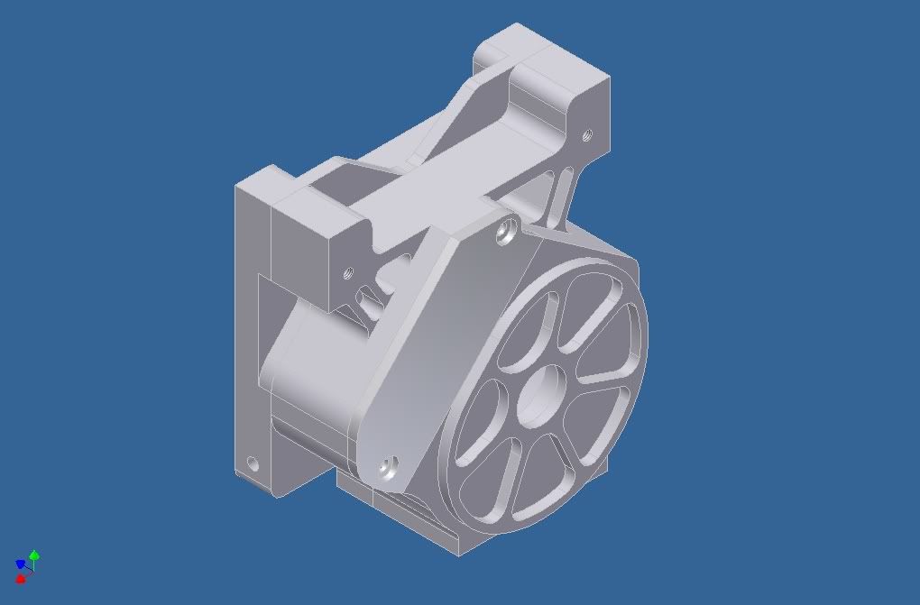 without cover: 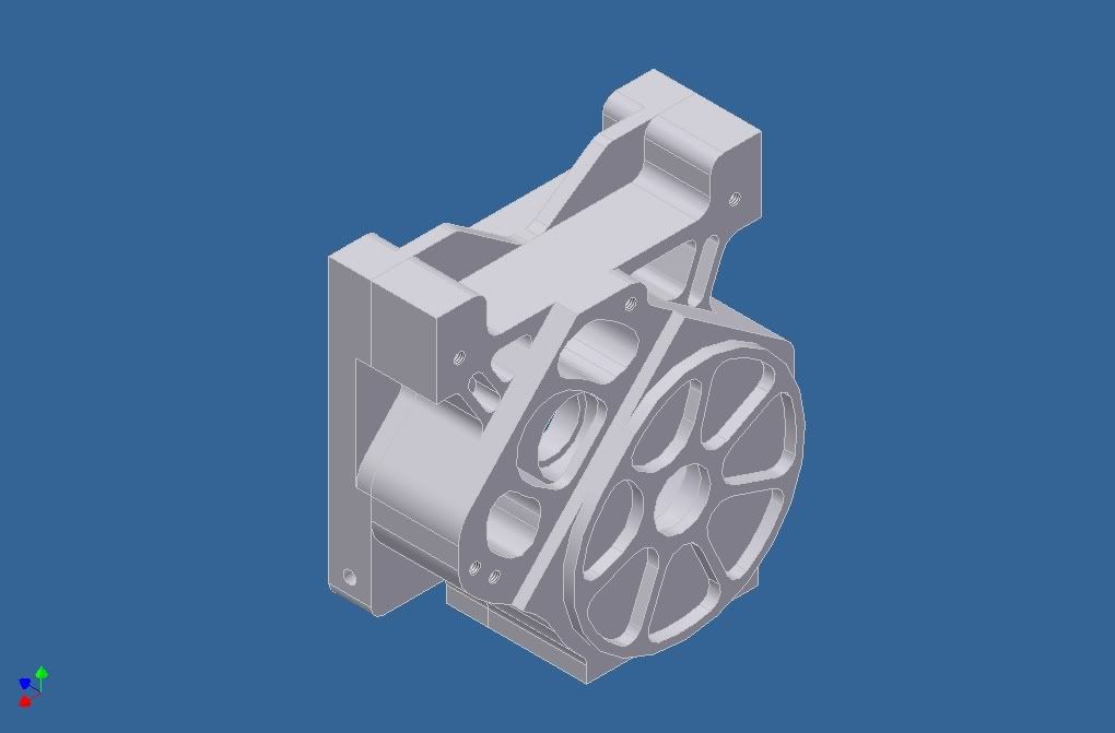 other pics: 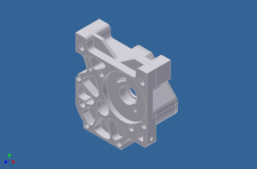 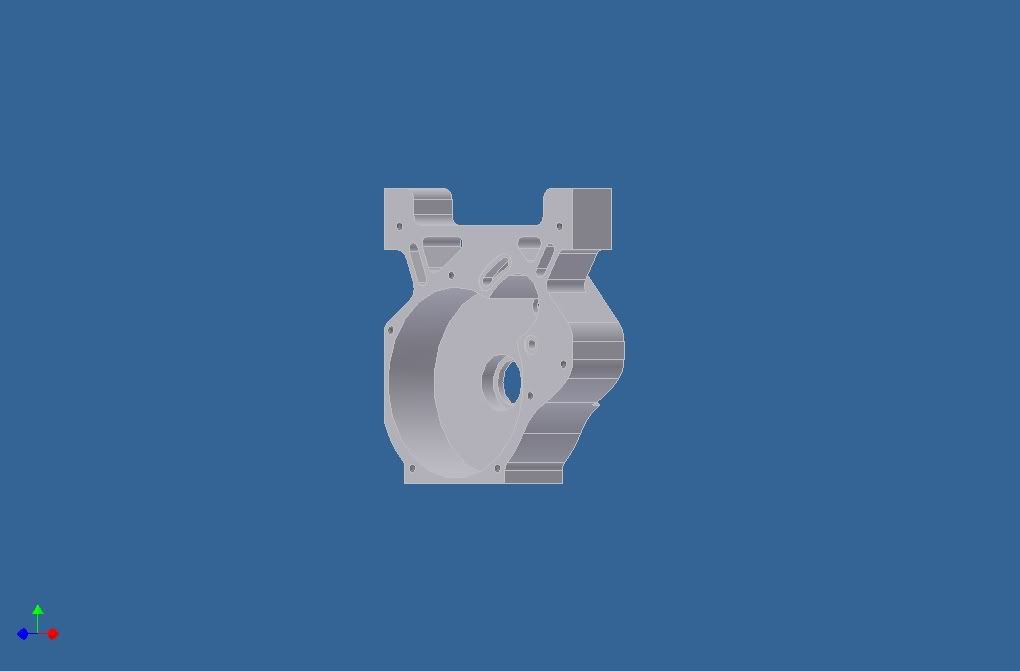 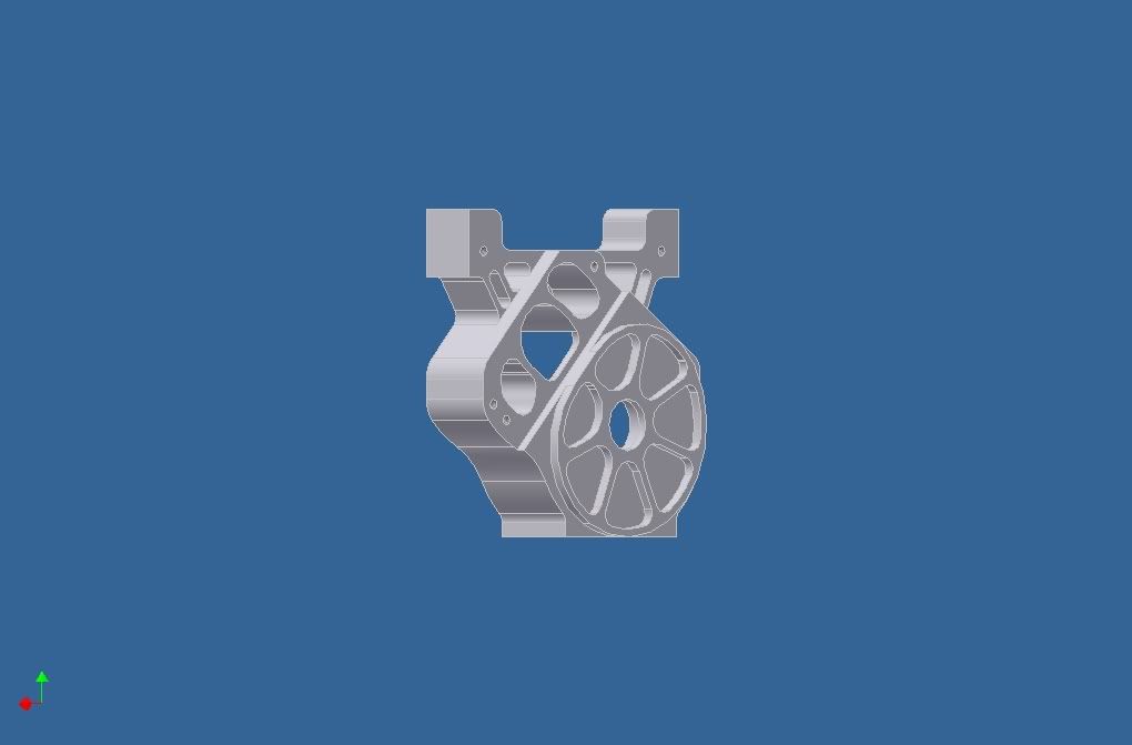 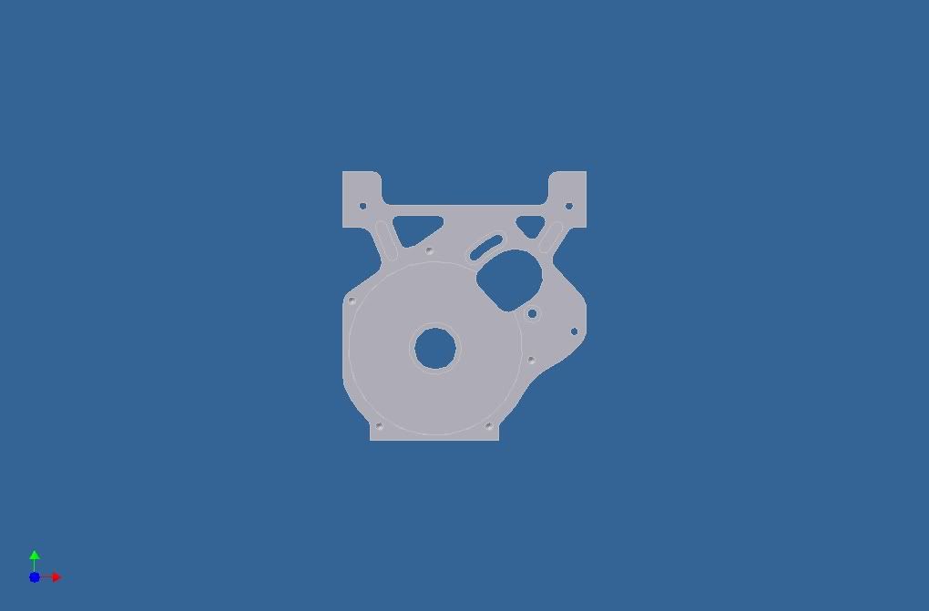 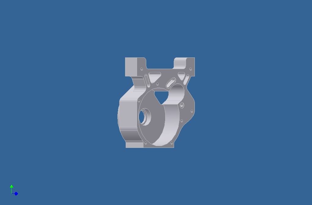 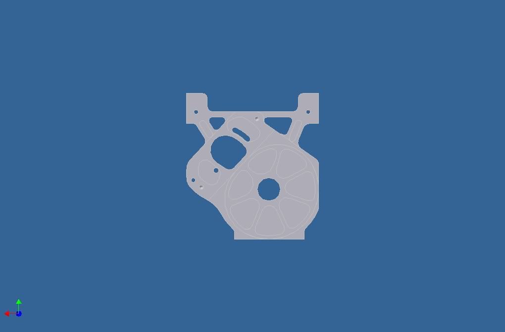
|
|
|
|
|
|
|
|
(#5)
|
|
RC-Monster Carbon Fiber
Offline
Posts: 339
Join Date: Aug 2005
Location: Indiana
|
04.20.2009, 03:35 AM
Wow!! It looks really great and I bet those who intend to put the Slipperential in their Savage might be interested. But I think its going to cost a lot to get this case fabricated..
|
 |
|
|
|
|
|
(#6)
|
|
RC-Monster Mod
Offline
Posts: 2,487
Join Date: Feb 2005
|
04.20.2009, 06:40 AM
We are building a slipperential savage. With parts from Mike. If you want I can post some pictures....
cheers Daf |
|
|
|
|
|
|
|
(#7)
|
|
RC-Monster Carbon Fiber
Offline
Posts: 339
Join Date: Aug 2005
Location: Indiana
|
04.20.2009, 06:49 AM
Daf, please post some pics on what you guys are working on. Extremely interested to see what Mike has to offer to the savage owners.
|
|
|
|
|
|
|
|
(#8)
|
|
RC-Monster Mod
Offline
Posts: 2,487
Join Date: Feb 2005
|
04.20.2009, 07:43 AM
Will do! As soon as I get the chance to upload some pics, maybe tomorrow night.
|
|
|
|
|
|
|
|
(#9)
|
|
RC-Monster Carbon Fiber
Offline
Posts: 214
Join Date: Dec 2007
Location: Ontario, Canada
|
04.20.2009, 08:54 AM
You can sign me up to buy one of those if they get made, nice design!
|
|
|
|
|
|
|
|
(#10)
|
|
RC-Monster Carbon Fiber
Offline
Posts: 62
Join Date: Nov 2008
|
04.20.2009, 11:48 AM
Ya, I'd be interested in seeing what you guys are coming up with too. Proly be a lot cheaper too, lol. I had 2 main goals for this box: 1) have the gearobx/motor as far forward as possible and 2) have the gears sealed so devris doesn't damage them.
Third less important goal was low CG EDIT: I lied, I actually had 3 main goals. THe thrid was to make it machinist friendly. It is designed so that it can be meilled on any 3-axis mill without the use of any soft jaws (becasue there is a good chance I may be machining it myself at the techshop, and if I am not, it will proabbly reduce fab costs). It has parrallel sides so its can be viced up easily. Low cg is 4th, less important goal. EDIT 2: TO admin (or another knowlegable person): I still need to know the distance between the bearings. I also need to the distance from the bearing to the slipper adjustment so I can make a opeining in the case for the tool to fit through. Also want to know if the stock cups will work with stock savage dog bones, as well as waht there diameter is. |
|
|
|
|
|
|
|
(#11)
|
|
Check out my huge box!
Offline
Posts: 11,935
Join Date: Aug 2007
Location: Slidell, LA
|
04.20.2009, 12:11 PM
Hey Spiffy, I like the enclosed box idea. Doing this would also allow you to lubricate the gears with something, which will also help wear. Not sure if you could run the slipperential in an oil bath due to the pad design, but some dr lube or grease would work ok.
As for the little removable cover, you could make that out of something clear like plexi/polycarbonate. That way you could check the mesh without removing it. Just to verify - you have designed it to hand the make gearing of 12/50? What diameter motor did you design around? I see that you have the motor mount face recessed into the plate, could it be designed to have the mount area flush with the face of the casing? That way different diameter motors could be used? I know that there is only so much space between the tvps on the savage, and I am sure your design takes that into account. Very interesting, I would like something similar to this for my savage! Jut did some math, and you may have some motor clearance issues with the 46/9 gearing. The diff output diameter is something like 15+mm. Depending on the diameter of motor used it may contact the diff output when smaller pinions are used... |
|
|
|
|
|
|
|
(#12)
|
|
|
KillaHurtz
Offline
Posts: 2,958
Join Date: Apr 2006
Location: Bucks Co, PA
|
04.20.2009, 12:24 PM
Quote:
Question tho, are you planning on a direct drive unit, or some sort of gear reduction (ie a one spd tranny, like some of the first version slipperentials?) That was a big stumbling block I was running into. A big spur hangs out the bottom or has to have unfriendly driveline angles (for high mounting.) Likewise, a small spur fits nicer, but offers little gear reduction, even with a small pinion. EG, w/ a 10T pinion & 46T spur, on the stock diffs you only get a ~15.9:1 FDR. Not much if you have a heavy savage and big 40 series tires. Forget about running the Cen diffs w/ their 2.89 ratio. G/L, I hope to see what you come up with. |
|
|
|
|

|
|
|
|
(#13)
|
|
|
RC-Monster Carbon Fiber
Offline
Posts: 62
Join Date: Nov 2008
|
04.20.2009, 12:57 PM
Quote:
I did the math,and with the neu-castle motor, the closest mesh you can get is one with 48:9, not 46:9. 46:9 is a tad high for the savage anyways. In fact, 48:9 is a tad high too. 50:9 and 50:10 are ideal ratios. If I do decide to sell these, I will be fabricating them at the techshop, as it is too expensive for mew to have someone else fabricate them if I sell them (i.e., I have to mark up the marked up price, which will make it insanely expensive). If I fab them myself, I can sell them at a reasonable price. Also, I can change individual ones for different motors and hole patterns, as only the main plat would have to change. The "cup" part would be the same for all of them. Another cool feature I didn't mention is that the screw hole for mounting the motor is completely counterbored, and the cup goes on top, leaving enough space for your allen wrench, but not allowing the screws to fall out. This means you can easily remove the motor and put it back in without having to reseat the screws. This makes changing motors and pinions easy while leaving the gearbox in the truck. I don't know if that makes sense, so if it doesn't I'll try and get soem pics of it. EDIT: It can handle 50:12. An easy way to see if the gearing will work is 48:9 + 6 teeth anywhere. (you can add 2 to one side, and 1 to the other, or 3 to one side, and none to the other). Mod 1 gearing works out such that increasing either the pinion or spur by 1 tooth will increase the distance between the shafts by .5 mm (it increases the mesh diamter of that gear by 1mm). I have my ratios set as follows. Based off the distance for 48:9, you can go in an additional 1.5mm (on only one side, so a total shoaft movement of .75). Round 1.5 down to 1, for a 1 tooth reduction, (but the motor may interfere with the cup). You can go out an addition 6.5mm (shaft movement of 3.25mm), so round 6.5mm down to 6 for 6 additional teeth possible (You will still have about 1mm between the motor and chassis if the motor is ALL the way out to 6.5mm, which it never will be, because it won't be in mesh with anything there. I made a typo above, which I will fix. The max distance is with 50:13 or 48:15 (both of which are WAYYY too high for a savage). Basically, although I didnt have intentions of selling, I kept speed demons in mind jsut in case I do decide to sell. |
|
|
|
|
|
|
|
|
(#14)
|
|
|
RC-Monster Carbon Fiber
Offline
Posts: 62
Join Date: Nov 2008
|
04.20.2009, 01:09 PM
Quote:
|
|
|
|
|
|
|
|
|
(#15)
|
|
|
Check out my huge box!
Offline
Posts: 11,935
Join Date: Aug 2007
Location: Slidell, LA
|
04.20.2009, 01:27 PM
Quote:
Given your info, it looks like your design will handle 46/16 gearing. Since you have designed it to fit the neu/castle motor, it will fit a smooth can neu just fine. I have a special project that will use a 1527 2y motor (625kv) on 10s lipo, which makes for low motor rpms. I was going to lock the X tranny locked in second gear, and use 47/23 gearing, but I am not sure if the tranny can handle it. That motor can make some torque, and the vehicle will not be light. Not sure if I would use a std diff, or Mike's slipperential. As for your question on the bearing to bearing dimension, it should be the same as a losi 8 diff (I think that is the diff with the smallest spacing). Mike made the diff to fit most 8th buggies, and it requires shimming between the bearings and the bulkheads to fit some of the brands. I would make yours to fit a std hotbodies/ofna/kyosho diff, and the slipperential will fit (may need shimming) and will alos allow the largest number of available diffs to fit. I would most likely use a hpi al diff cup with a kyosho plastic spur, as the plastic will provide some shock protection, and run a bit cooler than steel on steel. And I could grease it since your design is sealed. My other question is are you using stock chassis holes to mount it? Or do you plan to drill the chassis? Either is fine with me, as I would make my own tvps... |
|
|
|
|
 |
«
Previous Thread
|
Next Thread
»
| Currently Active Users Viewing This Thread: 1 (0 members and 1 guests) | |
 Linear Mode

|
|

Powered by vBulletin® Version 3.8.11
Copyright ©2000 - 2026, vBulletin Solutions Inc.
vBulletin Skin developed by: vBStyles.com
Copyright ©2000 - 2026, vBulletin Solutions Inc.
vBulletin Skin developed by: vBStyles.com