

|
|

|

|
(#1)
|
|
I have no idea what's going on
Offline
Posts: 464
Join Date: Jan 2005
Location: UK
|
06.13.2008, 06:47 PM
Cool, thanks for the info! If they have those discs on, then hopefully soldering wouldn't be a problem as you say. I have a 50W temp-controlled iron, so that might be just about up to it. I'd like a decen,t long runtime with this machine so 1P is out of the question, but 6S2P might work. I've been eyeing up the Elite 4800 25C LiPos, which apparently perform nicely. A 6S pack would be tall, but I could lay it on its side in a custom-sized tray which would also prevent the bottom cell from having to deal with the weight of all the others in a landing.
Sorry guys, I know, I'm indecisive...both cells have good points! I'll probably go LiPo on this occasion like I say, but the A123 info is very helpful still.  Whats_Nitro: Right, I got it now! A DDOR setup won't work on the Havoc without re-designing most of the truck, as it's just a 3-gear lateral transmission; nowhere near as easy to install a DDOR as it is in a normal, 4WD truck. But thanks for the idea nevertheless! |
|
|

|
|
|
|
|
(#2)
|
|
I have no idea what's going on
Offline
Posts: 464
Join Date: Jan 2005
Location: UK
|
09.25.2008, 10:22 AM
H'okay! Time for a bit of an update. I finally found the time to finish CAD'ing-up the parts for the motor mount
 . The design's deliberately very simple in order to keep costs down and beefiness up, but should do the job: . The design's deliberately very simple in order to keep costs down and beefiness up, but should do the job:Base plate: 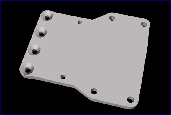 Motor plate: 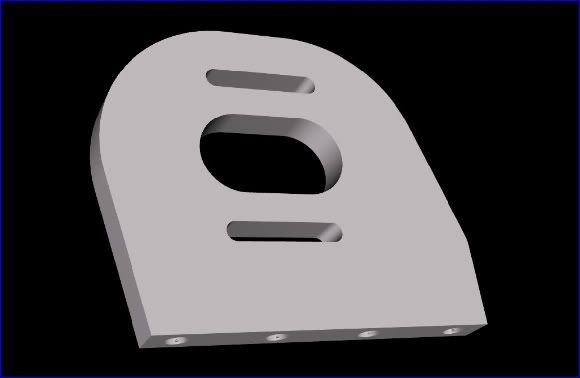 The base plate will be 5mm aluminium, and will bolt onto the Havoc chassis using pre-existing holes; the four engine mount holes, and then two others that I think are for if you install the fairly pointless upgrade chassis brace. It's so big because I wanted to make sure that the chassis was braced like it is in stock form, which is why it mounts over where the engine would be. These holes will be threaded, to keep things clean and tidy. This also gives a solid base for the motor to work from. The plate is actually upside down in this pic, showing the four countersunk M4 holes where the motor plate screws will pass through. The countersinks allow the plate to sit flush against the chassis when the screws are in. The motor plate itself is 6mm aluminium, and simply screws onto the base plate via the four M4 screws. Since the Castle Neu 1515 motor is 75mm long, there *might* be slight fitment issues with the rollbar mount the other side of the chassis...so I'll have to see on that. It'll be a close call. Might just have to move/fettle the rollbar, if it comes to it. I'm getting these parts made by a CNC machinist over here in the UK, and they should be done by the weekend. Now I just have to wait for the CastleNeu motor to be released, and for the MMM V3... Thanks for looking. 
|
|
|
|
|
|
|
|
(#3)
|
|
RC-Monster Carbon Fiber
Offline
Posts: 135
Join Date: Oct 2007
Location: Munich, Germany
|
09.26.2008, 01:15 AM
Wow, that looks really nice. It will be a fantastic car.
 I also often thought about A123 Cells but i stayed at my lipos because my soldering skills are not the best and the cells are heavy in comparison to lipos. I think if you are protecting your lipos with a tray, they should be 100% bashproof.
|
 |
|
 |
| Tags |
| great build!, one helluva havoc! |
«
Previous Thread
|
Next Thread
»
| Currently Active Users Viewing This Thread: 1 (0 members and 1 guests) | |
| Thread Tools | |
| Display Modes | Rate This Thread |


 Hybrid Mode
|
|

Powered by vBulletin® Version 3.8.11
Copyright ©2000 - 2026, vBulletin Solutions Inc.
vBulletin Skin developed by: vBStyles.com
Copyright ©2000 - 2026, vBulletin Solutions Inc.
vBulletin Skin developed by: vBStyles.com