

|
|

|

|
(#1)
|
|
RC-Monster Mod
Offline
Posts: 6,254
Join Date: May 2005
Location: Baton Rouge
|
03.10.2006, 06:01 PM
if you read the thread, it was brought up that he had the batteries in the front but there really in the rear were the engine use to be.
|
 |

|
|
|
|
|
(#3)
|
|
RC-Monster Stock
Offline
Posts: 16
Join Date: Jul 2006
|
07.11.2006, 06:48 PM
it is possible that he tore a hole in the universe and was sucked into a blackhole upon full throttle 10S acceleration...
|
|
|
|
|
|
|
|
(#4)
|
|
RC-Monster Admin
Offline
Posts: 10,480
Join Date: Feb 2005
|
07.11.2006, 06:51 PM
Sounds like a reasonable excuse to be late at a date..
|
|
|
|
|
|
|
|
(#5)
|
|
RC-Monster Titanium
Offline
Posts: 1,256
Join Date: Jan 2006
Location: Canada
|
07.12.2006, 12:03 PM
as i read on this thread that savy just getts better and better!
VIDEO PLEASE WHERE ARE YOU!! |
 |
|
|
|
|
|
(#6)
|
|
Guest
Posts: n/a
|
01.16.2008, 05:04 PM
Time to Ressurect this thread, as well as my passion for this hobby. I suddenly quit 2 years ago and don't really know why, I sort of just got sucked into black hole! I have an HPI Baja 5B now (which is awesome) that I run occasionally, but I really want to see this project finished. The way I went around making this, I cut a few corners. This time around I'm not going to do that. The motor mount won't have any plastic incorporated into it like before, and I still have to find some way to protect the spur from being ripped in two. Finishing this is part of my new year's resolution. I have to finish it, I just have to! Since I last posted, it hasn't gotten a single run, it's still just a baby.. THE POWER MUST BE UNLEASHED!
 Overall, the concept, general layout, and idea is great (in my opinion) but I have to improve the execution. From the top of my head I have to: -Find a better way to mount the LST shocks, the current way is much too loose and weak for my liking. -Give it the full stainless steel screw treatment -Create a new motor mount system that is more sturdy -Create a better center slipper and mount (diff maybe? probably not) -Tighten up the suspension in general (the top A-Arms are needing of adjustment particularily) -Figure some way to protect the innards of the truck (I'm thinking of a thin sheet of lexan) -Refamiliarize myself with the electronics and tech behind the project in general. I'll be revisiting this project and thread soon enough, my first agenda is to design a new motor mount, possibly getting it machined professionally. I'll try to keep you updated. |
|
|
|
|
|
|
|
(#7)
|
|
Guest
Posts: n/a
|
01.29.2008, 06:28 PM
Well, I have good news, and bad news.
I designed a somewhat simple motor mount on some free CAD software (eMachineShop), and I got some quotes. Lowest I can seem to get is around $150-$200 US for a single production. So, it seems that getting it milled is pretty much out of the equation. I think I will just have to try and fabricate it myself (grrr), unless somebody knows somebody/someplace that could do it for cheap. It's not too complex of a piece, 1cm thick, milled out to 5mm around the motor, with 9 motor holes. I'll post some pictures of it when I get home. |
|
|
|
|
|
|
|
(#8)
|
|
Old Skool
Offline
Posts: 7,494
Join Date: Feb 2007
Location: Devon, England
|
01.29.2008, 06:56 PM
I would have said Mike normally, but since he is permanently busy... maybe Dafni or the Candyman even- he has verical mill & rotary table, and makes awesome stuff from lumps of metal.
|
|
|
|
|
|
|
|
(#9)
|
|
Guest
Posts: n/a
|
01.30.2008, 01:52 AM
Well, here are the pictures. It's a pretty cheap program, but this would be a basic mockup. I think I am going to purchase Solidworks or Autocad, and then I can draw in there. The mount is 10mm thick, and the place where the motor would be placed is milled out 5mm.
Front:  Back: 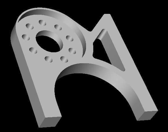 I think I may, after the purchase of a better CAD program, just create my dream of a project, my own TVPs, slipperential, battery mounts, etc through CNC. I think I may just go with a simple motor mount for now untill then though, just to get it running. Thanks! Edit: You also may notice that there is 0 adjustability on the mount itself. I have a way to adjust it, but it is a surprise! Edit 2: Uh oh, I just bought Solidworks Student Edition for $90! Looks like I'm going to end up designing my own TVPs, TVP braces, Slipperential, ESC/radio tray, etc. Might as well continue to go full out on this project, right? This is going past insanity.. I think.. |
|
|
|
|
|
|
|
(#10)
|
|
Guest
Posts: n/a
|
02.12.2008, 05:28 PM
Solidworks finally came in the mail, I just have to learn how to use it!
 I have some good ideas in my head that I can't wait to draw down for everyone to see, I just have a few questions.. In a slipperential setup, will a Revo slipper be able to handle the abuse I'm going to put it through, or should I try a sprong slipper sort of setup? I've also seen that new single piece slipperential, which looks promising.. but would that be able to handle the power? I'm also planning on extending the chassis even more than the FLM one is (probably another 30-40mm), does anyone know of any bodies that won't look goofy? Thanks! |
|
|
|
|
|
|
|
(#11)
|
|
RC-Monster Mod
Offline
Posts: 5,297
Join Date: Mar 2005
Location: SoCal
|
02.12.2008, 06:00 PM
The Revo slipper worked well on my "slipperential" with a 7XL and 5s2p, when I had that Revo. To my knowledge noone has used a slipperential with much more power than that, and few people have them (since they are designed for racing).
|
|
|
|
|
|
|
|
(#12)
|
|
|
Guest
Posts: n/a
|
02.12.2008, 06:16 PM
Quote:
|
|
|
|
|

|
|
|
|
(#13)
|
|
Check out my huge box!
Offline
Posts: 11,935
Join Date: Aug 2007
Location: Slidell, LA
|
02.12.2008, 06:39 PM
I can say that the revo slipper is pretty tough. If you are going use it for acceleration limiting like 10th scale it will wear quickly. But if you are using it for gear/drivetrain protection you should be ok (slipper set reasonably tight). I have metalman's old revo with the slipperential and it works fine for me. I am actually going to hold off on my other revo project until the center diff with the integrated slipper is released. That looks like the most promising method to me!
|
|
|
|
|
|
|
|
(#14)
|
|
|
Guest
Posts: n/a
|
02.12.2008, 06:54 PM
Quote:
|
|
|
|
|
|
|
|
|
(#15)
|
|
Check out my huge box!
Offline
Posts: 11,935
Join Date: Aug 2007
Location: Slidell, LA
|
02.12.2008, 06:58 PM
The lack of gearing is a good point. I will use an outrunner so I will have a slower turning, higher torque motor. The lack of gearing will not cause me too much of an issue due to that motor choice. The std slipperential with the added gear reduction works well. If I made one for myself, I would use a 46t diff gear, as it would affort more space for a similar sized spur gear, that would not contact the diff output on the slipper side of the assembly. I usually run 46t spurs (modified mgt spurs to fit the revo slipper).
|
|
|
|
 |
«
Previous Thread
|
Next Thread
»
| Currently Active Users Viewing This Thread: 1 (0 members and 1 guests) | |

 Hybrid Mode
|
|

Powered by vBulletin® Version 3.8.11
Copyright ©2000 - 2025, vBulletin Solutions Inc.
vBulletin Skin developed by: vBStyles.com
Copyright ©2000 - 2025, vBulletin Solutions Inc.
vBulletin Skin developed by: vBStyles.com