


|

|
(#16)
|
|
Soldermaster Extraordinaire
Offline
Posts: 4,529
Join Date: Apr 2007
Location: Plymouth, MA, USA
|
04.15.2010, 10:35 PM
Does this help? I've gone over it a few times and it seems correct...
|
|
|

|
|
|
|
|
(#17)
|
|
RC-Monster Carbon Fiber
Offline
Posts: 119
Join Date: Mar 2010
|
04.16.2010, 12:00 AM
Look at you! lol
I just spent an hour marking up the same drawing and I stop back in here to see you got me covered. lol Clearly What's nitro has this better covered than I did. Seems to be right. Coil tie in's. The large coil has 5-wire tie in's denoted in purple. The smaller 2-coil has it's 4-wire tie in's in blue. 12v power is in yellow. 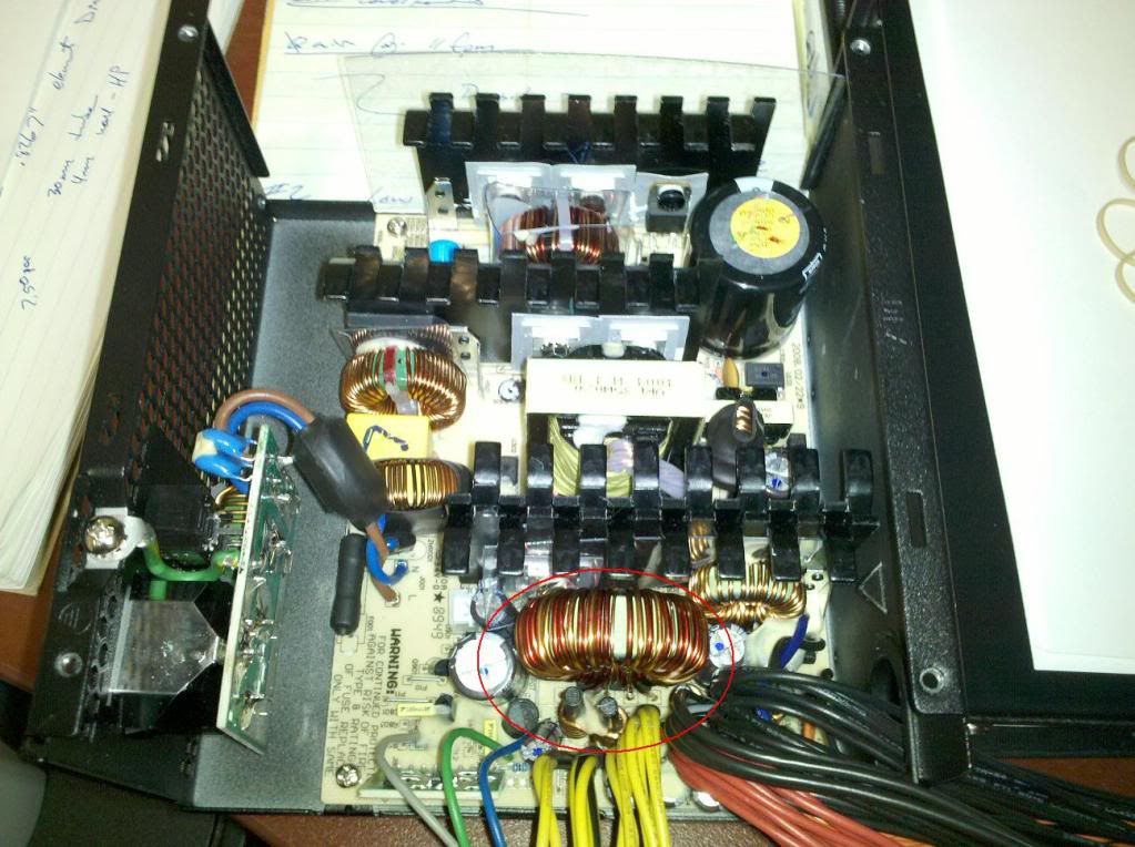 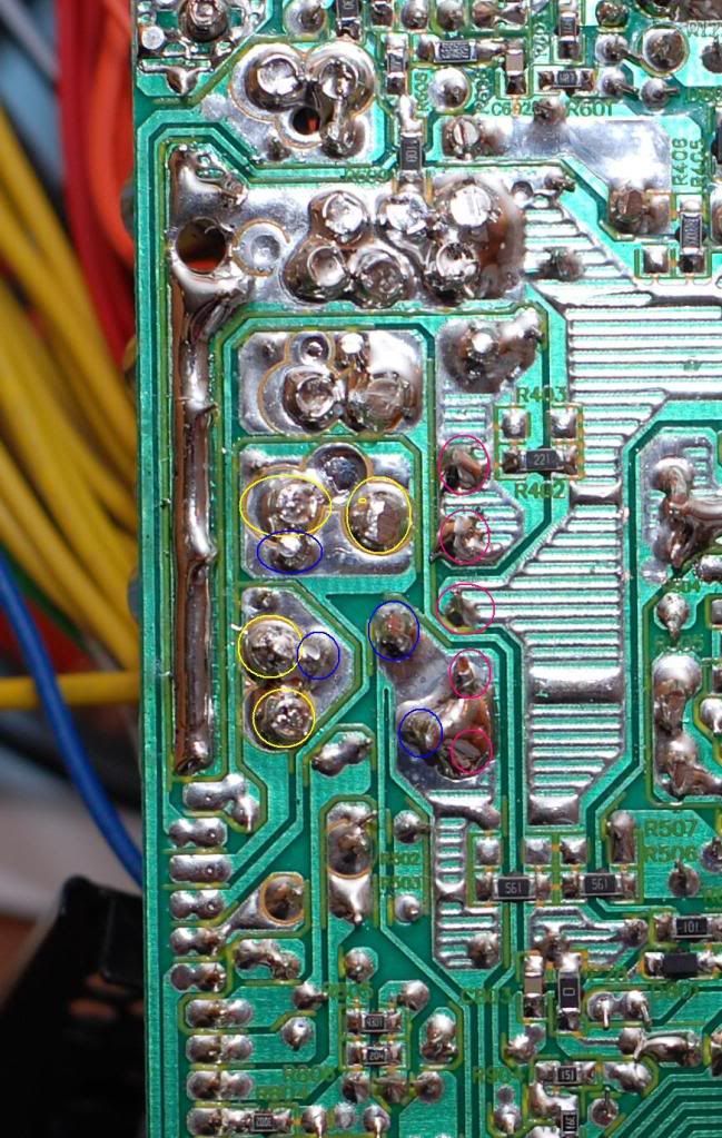
|
|
|
|
|
|
|
|
(#18)
|
|
Soldermaster Extraordinaire
Offline
Posts: 4,529
Join Date: Apr 2007
Location: Plymouth, MA, USA
|
04.16.2010, 12:03 AM
Yeah some of my drawing needs to be shifted left a bit... Couldn't really tell based on the overhead view earlier in the thread. Close enough though!

|
|
|
|
|
|
|
|
(#19)
|
|
RC-Monster Carbon Fiber
Offline
Posts: 119
Join Date: Mar 2010
|
04.16.2010, 12:04 AM
Thanks again for the help here guys!
Much appreciated! |
|
|
|
|
|
|
|
(#20)
|
|
Soldermaster Extraordinaire
Offline
Posts: 4,529
Join Date: Apr 2007
Location: Plymouth, MA, USA
|
04.16.2010, 12:07 AM
No problem, man!
|
|
|
|
|
|
|
|
(#21)
|
|
RC-Monster Carbon Fiber
Offline
Posts: 119
Join Date: Mar 2010
|
04.16.2010, 12:07 AM
Not my best image. lol
|
|
|
|
|
|
|
|
(#22)
|
|
RC-Monster Carbon Fiber
Offline
Posts: 119
Join Date: Mar 2010
|
04.16.2010, 12:08 AM
So this begs the question then,,,,
Where/what should I tap into for the full rail current? |
|
|
|
|
|
|
|
(#23)
|
|
|
Soldermaster Extraordinaire
Offline
Posts: 4,529
Join Date: Apr 2007
Location: Plymouth, MA, USA
|
04.16.2010, 12:20 AM
Quote:
 
|
|
|
|
|

|
|
|
|
(#24)
|
|
RC-Monster Carbon Fiber
Offline
Posts: 119
Join Date: Mar 2010
|
04.16.2010, 12:26 AM
NICE!!!!
As you can see, I MS painted the crap out of mine too. lol What your showing seems completely feasible to me. Provided it's all being powered off the same rail, I don't think there would be any issue bridging that pad. Otherwise, I'm ditching all the 3.3 and 5v stuff anyway. Looks simple enough! Nice to see the east coast guys up late. lol I'm in CT. Thanks again! |
|
|
|
|
|
|
|
(#25)
|
|
Soldermaster Extraordinaire
Offline
Posts: 4,529
Join Date: Apr 2007
Location: Plymouth, MA, USA
|
04.16.2010, 12:32 AM
Yup. It is a single rail, but it splits into two leads through the choke coils. I think because in a PC there is a 12V ATX connector (for the Mobo) and the other 12V lead goes to the 6 pin PCIe and SATA connectors. I guess the choke coils arrest EMF feedback between the two leads??? That would suit their name... Since you only need one 12V+ lead to the charger I don't think the choke coils are necessary.
|
|
|
|
|
|
|
|
(#26)
|
|
RC-Monster Carbon Fiber
Offline
Posts: 119
Join Date: Mar 2010
|
04.16.2010, 12:44 AM
Perfect! Great information!
I'd also guess based on the ATX std, they generally keep the 12v feeders to below 18A I think. Maybe it's 15A but something like that. I found it in the white paper spec sheet for ATX power supplies. |
|
|
|
|
|
|
|
(#27)
|
|
Soldermaster Extraordinaire
Offline
Posts: 4,529
Join Date: Apr 2007
Location: Plymouth, MA, USA
|
04.16.2010, 12:56 AM
The 12V lines are connected directly to the full power output. The smaller traces coming off of the main pads are for the regulation. I would guess that if either pad goes over 15A, or maybe 20A for ATX and 10A for Acc., then it would trip the overcurrent sensor and shut down. There must be a main OC sensor on the other side of the big Xformer, but at least if you bypass the chokes you wont have to deal with the unnecessary secondary OC circuits. Or maybe they will see equal load and not trip anyways... IDK.
|
|
|
|
|
|
|
|
(#28)
|
|
RC-Monster Carbon Fiber
Offline
Posts: 119
Join Date: Mar 2010
|
04.16.2010, 10:59 AM
In the review I posted earlier, they stated the OC protection on the 400cx worked well. Matter of fact, they stated at the limit, the power supply was closer to a 500w unit.
Well, hopefully Brian can verify so I can get this thing sorted tonight 
|
|
|
|
|
|
|
|
(#29)
|
|
RC-Monster Admin
Offline
Posts: 14,609
Join Date: Nov 2005
Location: Des Moines, IA
|
04.16.2010, 11:04 AM
Hmm. I posted a response last night, but it didn't save for some reason. Anyhoo...
Do NOT bypass the coils. They are probably sampling coils for regulation, and you might get crappy performance under load. I would simply bridge the solder areas after the coils. |
  |
|
|
|
|
|
(#30)
|
|
RC-Monster Carbon Fiber
Offline
Posts: 119
Join Date: Mar 2010
|
04.16.2010, 11:30 AM
Sounds like we have a plan!
Let me work this up and I'll keep you guys posted tonight on how it goes. Hopefully we'll be charging this evening! Thanks again! |
|
|
|
 |
«
Previous Thread
|
Next Thread
»
| Currently Active Users Viewing This Thread: 1 (0 members and 1 guests) | |
 Linear Mode

|
|

Powered by vBulletin® Version 3.8.11
Copyright ©2000 - 2026, vBulletin Solutions Inc.
vBulletin Skin developed by: vBStyles.com
Copyright ©2000 - 2026, vBulletin Solutions Inc.
vBulletin Skin developed by: vBStyles.com