


|
|

|

|
(#1)
|
|
RC-Monster Mod
Offline
Posts: 6,597
Join Date: Apr 2007
Location: NJ
|
06.01.2009, 10:12 AM
Don't know what that linc guy is on - That what I was saying...
i.e. This is why it won't work This is a 4s battery Tap 1 Battery 1 Cell 1 (-) Tap 2 Battery 1 Cell 1 (+) / Cell 2 (-) Tap 3 Battery 1 Cell 2 (+) / Cell 3 (-) Tap 4 Battery 1 Cell 3 (+) / Cell 4 (-) Tap 5 Battery 1 Cell 4 (+) This is an attempt at a 2s 1p as 4s and why it doesn't work Tap 1 Battery 1 Cell 1 (-) Tap 2 Battery 1 Cell 1 (+) / Cell 2 (-) Tap 3 Battery 1 Cell 2 (+) / Battery 2 Cell 1 (-) / Battery 1 Cell 1 (-) - because the batteries are in parallel i.e. you will short the battery Tap 4 Battery 2 Cell 1 (+) / Cell 2 (-) Tap 5 Battery 2 Cell 2 (+) |
|
|

|
|
|
|
|
(#2)
|
|
|
Check out my huge box!
Offline
Posts: 11,935
Join Date: Aug 2007
Location: Slidell, LA
|
06.01.2009, 10:14 AM
Quote:
|
|
|
|
|

and the consensus is |
|
|
|
(#3)
|
|
Brushless Basher
Offline
Posts: 59
Join Date: Apr 2009
Location: Adelaide South Australia
|
and the consensus is -
06.01.2009, 10:32 AM
so if ive got this right and I use my balance charger to charge through both packs main leads siultaneously with the 2 2s taps converted to 1 2s tap I should be right (the packs are identical)
thanks for the input pls correct me if I'm wrong "Lipo batteries make everthing better!" PS i'll check your answer in the morning got to get up in5 1/2 hours |
 |
|
|
|
|
|
(#4)
|
|
|
Check out my huge box!
Offline
Posts: 11,935
Join Date: Aug 2007
Location: Slidell, LA
|
06.01.2009, 10:59 AM
Quote:
|
|
|
|
|
|
|
|
|
(#6)
|
|
RC-Monster Admin
Offline
Posts: 14,609
Join Date: Nov 2005
Location: Des Moines, IA
|
06.01.2009, 11:08 AM
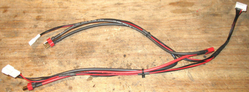
Maybe I should add a parallel charging/balancing diagram to my site...
|
  |
|
|
|
|
|
(#7)
|
|
|
Guest
Posts: n/a
|
11.14.2009, 01:23 AM
Quote:
I have some questions regarding your schematic under "Lipo Wiring" @ http://scriptasylum.com/rc_speed/_lipo.html. The example I will use is the 5S2P lipo configuration. I want to know what is represented by the wiring where the positive and negative junctions of each pack seem to be bridged to another adjacent pack? I also noticed that there is only one balance tap for this entire configuration. It seems to be independent of the number of packs that are put in parallel provided that each pack has the same number of cells since I changed the parameters just to makes sure for myself. This seems to contradict your instructions on how to make the Y harness. Hope you can clarify this for me. |
|
|
|
|


|
|
|
|
(#8)
|
|
RC-Monster Admin
Offline
Posts: 14,609
Join Date: Nov 2005
Location: Des Moines, IA
|
11.14.2009, 02:40 PM
The part you circled in greed is simply the bridge connection between each paralleled cell. A 5s2p pack is simply made up of two paralleled cells, with five of those pairs in series. The picture shows what looks like bus bars for the sake of example, but lipo cells are generally not shaped like that so the tabs would just the tied together to make the connection. A123 cells though, would have bus bars similar to that because of their shape. It simply comes down to the cell's physical shape and layout.
Yes, there is only one balance tap no matter how many paralleled cells there are. This is because the contact points for each paralleled cell are electrically the same point, so only one set of tap points are needed for each paralleled set. That drawing is only used if one wants to make their own lipo pack; it shows the electrical connections even though it might not look like that in the real world. This happens all the time in the electronics world where a schematic diagram never looks like the physical layout. A schematic is handy for the designer/builder/troubleshooter. A layout diagram would show the true physical layout of the components, but it is difficult to troubleshoot/build a circuit using this type of diagram. The diagram you circled is really a combination of a schematic and a layout diagram, hence the slight misunderstanding. Now, on the Y adaptor diagram, it assumes the individual packs were wired correctly, so from a connector standpoint, it does not matter if the packs are 2s1p or 2s200p. This diagram is to show how to wire a series charging/balancing harness when using two packs. I hope all that made sense! 
|
|
|
|
lipo configuration |
|
|
|
(#9)
|
|
Guest
Posts: n/a
|
lipo configuration -
11.15.2009, 12:35 AM
Hi Brian,
I am still confused about the whole bridge thing. If these cells were regular rectangular lipo cells (not A123), what would the bridge physically look like (the green thing I circled). Also, when you say "the contact points for each parallel cell are electrically the same point," if I have two packs in parallel, what does this look like as well? I just never seen or heard of these concepts before and this why I am asking. Thanks for your help. |
|
|
|
|
|
|
|
(#10)
|
|
Guest
Posts: n/a
|
11.15.2009, 01:18 AM
Okay so going back to the 5s2p example, would all the + terminals of the first pack go on top of all the + terminals of of the second pack and the same with all the negative terminals and not just the + and - terminals at the ends of both packs, which make up the power/discharge leads?
|
|
|
|
|
|
|
|
(#11)
|
|
RC-Monster Aluminum
Offline
Posts: 897
Join Date: Mar 2010
Location: Same town as "Brand P"
|
03.12.2010, 06:06 PM
Is this kinda the same thing? http://www.hobbyking.com/hobbyking/store/uh_viewItem.asp?idProduct=9910&Product_Name=2_x_3S_->_6S_Splitter_JST-XH__(5pcs/bag)
|
|
|
|
|
|
|
|
(#12)
|
|
RC-Monster Admin
Offline
Posts: 14,609
Join Date: Nov 2005
Location: Des Moines, IA
|
11.15.2009, 12:40 AM
With a regular rectangular lipo cell, a parallel pair would be made by simply putting the cells on top of each other so both + tabs are touching and both - tabs are touching. Then you just fold them together and solder.
If you have two seperate packs in parallel, you'd have two seperate balance plugs. There is no current drawing for that specifically. |
|
|
|
|
|
|
|
(#13)
|
|
RC-Monster Titanium
Offline
Posts: 1,884
Join Date: Jul 2009
|
03.12.2010, 11:02 PM
Yes, that is the same thing.
|
|
|
|
|
|
|
|
(#14)
|
|
|
RC-Monster Aluminum
Offline
Posts: 897
Join Date: Mar 2010
Location: Same town as "Brand P"
|
03.13.2010, 12:13 AM
Quote:
|
|
|
|
|
 |
«
Previous Thread
|
Next Thread
»
| Currently Active Users Viewing This Thread: 1 (0 members and 1 guests) | |

 Hybrid Mode
|
|

Powered by vBulletin® Version 3.8.11
Copyright ©2000 - 2026, vBulletin Solutions Inc.
vBulletin Skin developed by: vBStyles.com
Copyright ©2000 - 2026, vBulletin Solutions Inc.
vBulletin Skin developed by: vBStyles.com