


|

|
(#16)
|
|
RC-Monster Dual Brushless
Offline
Posts: 5,139
Join Date: Sep 2006
|
11.04.2007, 10:38 AM
One thing I have to add. As you all know there are some delays with m ESC, but the engineer that is building it told me that it would be easier to make a 80 or 100 volts controller. I already told him I will do a few after I receive the one I'm waiting for. Just te thought of having a ESC capable of 18S and 22S lipos just makes me happy LOL. I think I like HV stuff mainly because I got electrocuted twice. First time was in Brasil with 220 volts, I was 7yrs old. The other time was in HS in Florida. It was from a nasty Hi Amp Audio Grade battery that knocked me a few feet back LOL.
|
 |

|
|
|
|
|
(#17)
|
|
RC-Monster Admin
Offline
Posts: 14,609
Join Date: Nov 2005
Location: Des Moines, IA
|
11.04.2007, 03:34 PM
If you like that, you should check out a TV flyback transformer sometime! Don't know if it would produce enough current to kill, but the voltage sure hurt!
|
 |
|
|
|
|
|
(#18)
|
|
|
RC-Monster Dual Brushless
Offline
Posts: 5,139
Join Date: Sep 2006
|
11.04.2007, 04:20 PM
Quote:
|
|
|
|
|

|
|
|
|
(#19)
|
|
RC-Monster Admin
Offline
Posts: 14,609
Join Date: Nov 2005
Location: Des Moines, IA
|
11.04.2007, 05:50 PM
Yeah, that's 12,000v. Usually, since the voltage is stepped up, the current is stepped down so there isn't much current available. But, it only takes ~15mA to kill (that's 0.015A)...
|
|
|
|
|
|
|
|
(#20)
|
|
RC-Monster Dual Brushless
Offline
Posts: 5,139
Join Date: Sep 2006
|
11.04.2007, 06:00 PM
Good thing for fuses and circuit breakers LOL.
|
|
|
|
|
|
|
|
(#21)
|
|
RC-Monster Brushless
Offline
Posts: 2,085
Join Date: Sep 2007
|
11.04.2007, 06:13 PM
I decided to take a few pictures of this HV power board before I completely tear down the original configuration and perhaps learn a few things from analyzing what they've done.
I notice that they have all the gate leads tied together through a series on resistors inline. I'm not sure what effect this will have, but I think it governs the amperage the gate leads are allowed to draw. The Blue Component marked "Wima" is like a small Capacitor, it will charge up under an Ohm meter. This is connected between the source and the drain. A Cushion? I would think they need to charge up first, before full output power is seen. 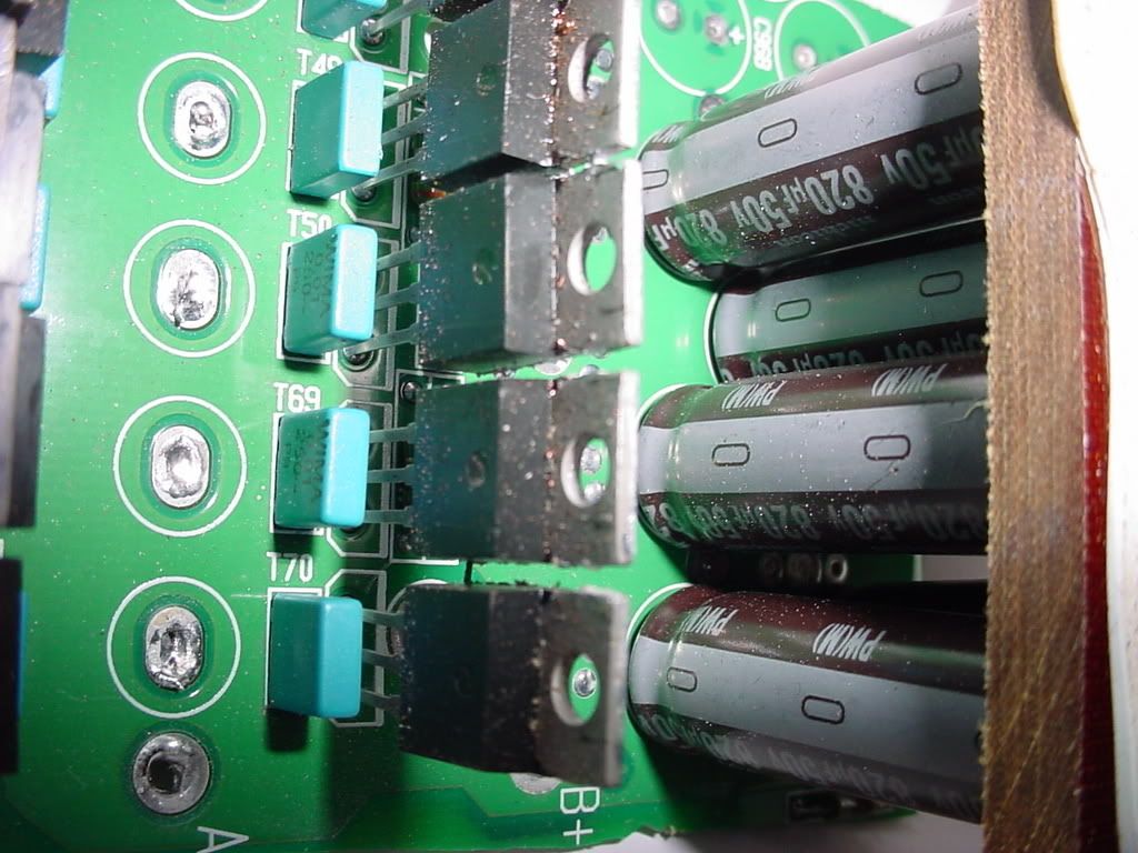 Wait second! Are those more Low ESR Capacitors I see? (*Joke*) 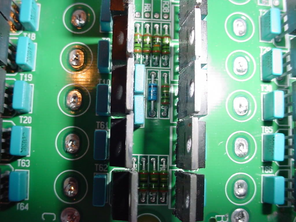 I'm thinking about using this board for testing. Strip the resistors, and use the existing pathways for the Mosfets. The Caps are already in place too. This thing is huge though. It's 8" x 3" x 2". If I can make it work and put it through some testing, I'll reconfigure the entire thing to make it compact. Absolute ratings for this board is 375 amps. Perhaps it will do 300 amps continous with the proper heat sinking. (which I have also) Come to think of it, How am I going to test this thing? I know a Data Logger is in order, but to seriously load it? Hmmmmm...........aah well, one thing at a time. I have a AXI 4130/20 that I could bolt a 20" inch prop onto. It's rated for 8 Lipo cells. Maybe open up the doors and blow the house out. LOL |
|
|
|
|
|
|
|
(#22)
|
|
|
RC-Monster Brushless
Offline
Posts: 2,085
Join Date: Sep 2007
|
11.04.2007, 06:17 PM
Quote:
Please keep us updated Lutach. You sure have my interest in that. But please, be careful around all those flowing electrons. LOL |
|
|
|
|
|
|
|
|
(#23)
|
|
RC-Monster Dual Brushless
Offline
Posts: 5,139
Join Date: Sep 2006
|
11.04.2007, 06:26 PM
I will keep everyone informed, but I might wait until I have one unit here for testing. Now I'm really liking your controller. Size wise, yes it looks big, but the power you might be capable of producing, the size of the controller will not matter. Keep me informed on how good your monster (In a good way) performs.
|
|
|
|
|
|
|
|
(#24)
|
|
RC-Monster Brushless
Offline
Posts: 2,085
Join Date: Sep 2007
|
11.05.2007, 08:27 AM
Thanks Lutach
This powerboard has 30 of the larger 80v 75amp Mosfets. This will be a hefty gate load for the drivers to carry. This is why I need to study Brain Board Components alot closer to calculate driver load carrying ability. |
|
|
|
|
|
|
|
(#25)
|
|
|
RC-Monster Dual Brushless
Offline
Posts: 5,139
Join Date: Sep 2006
|
11.05.2007, 11:31 AM
Quote:
|
|
|
|
|
|
|
|
|
(#26)
|
|
RC-Monster Brushless
Offline
Posts: 2,085
Join Date: Sep 2007
|
12.15.2007, 12:50 PM
Yesterday, my Quark 80 amp died. It still blinks the red "heart beat" at the led's. It also lights different led's with different throttle positions on the controller. No power is being sent to the motor.
I suspect the problem is on the power board. I hope it is. Can I adapt the brain board to work with this larger power board? That's what I'm thinking about doing. It would be a 6S ESC that would kick butt. The larger power card will do 300amp at 36 volts. That would be 450 amps on 6S. |
|
|
|
|
|
|
|
(#27)
|
|
Brushless Heavy Weight....
Offline
Posts: 1,954
Join Date: Sep 2005
Location: Kingsville, Ontario
|
12.15.2007, 02:27 PM
When you guys have the ESCs ready.. I'll be sh*ttin' my pants to test it out.. I've gotta make use of all my lipos...
http://www.geocities.com/aqwut 1HP (electric) = 746 Watts. Everything is brushless!! |
|
|
|
|
|
|
|
(#28)
|
|
|
Z-Pinch racer
Offline
Posts: 3,141
Join Date: Nov 2006
Location: SK, Canada
|
12.15.2007, 07:14 PM
Quote:
 Come stop by and I will show you my 'Tesla Coil' running at ~700,000volts AC... very load, and looks VERY deadly, however you can hold you hand in the arcs and you only feel very minor shocks... that's because it's running at very high frequencies ~500khz resonant freq. I have heard of ppl using those flyback transformers in small Tesla Coils for the primary circuit. |
|
|
|
|
 |
«
Previous Thread
|
Next Thread
»
| Currently Active Users Viewing This Thread: 1 (0 members and 1 guests) | |
 Linear Mode

|
|

Powered by vBulletin® Version 3.8.11
Copyright ©2000 - 2026, vBulletin Solutions Inc.
vBulletin Skin developed by: vBStyles.com
Copyright ©2000 - 2026, vBulletin Solutions Inc.
vBulletin Skin developed by: vBStyles.com