RC-Monster Forums  

Go Back   RC-Monster Forums > RC-Monster Area > General Discussion

Reply
 
Thread Tools Rate Thread Display Modes
Old
  (#16)
rawfuls
roofles.
 
rawfuls's Avatar
 
Offline
Posts: 1,982
Join Date: Oct 2008
Location: Woodland Hills, CA
01.10.2011, 08:11 PM

Quote:
Originally Posted by whitrzac View Post
I haven't read the thread, but the wall of text says that you guys are going at this waaaay too much...

hook them to the 5v rail and be done with it...
Well I'm trying to setup a switch that would differentiate from 5V to 12V, and Off.. and such.

It's a wall of text because I'm electrically stupid...

--

EDIT:
Found a cool article while surfin' da webz.

http://www.silentpcreview.com/article6-page1.html

Pretty much talks about how to get 5V, 7V, or 12V through a switch, without using diodes..

Are there any cons to that version over Brians?
Thanks guys, and sorry for the excessive questions!

Last edited by rawfuls; 01.11.2011 at 12:36 AM.
  Send a message via AIM to rawfuls Send a message via MSN to rawfuls  
Reply With Quote
Old
  (#17)
rawfuls
roofles.
 
rawfuls's Avatar
 
Offline
Posts: 1,982
Join Date: Oct 2008
Location: Woodland Hills, CA
01.12.2011, 08:51 PM

Hey guys, was kinda bored in math class earlier today, so thought why not draw out what I'm gonna do?

Anyways, I still have a question; how many and what diodes will I need to drop a 12V connection to 5V?
Or how do I find how much voltage a diode will drop? So that way I can figure out which diode I will need...

Here's what I have so far...
A rough diagram:
  Send a message via AIM to rawfuls Send a message via MSN to rawfuls  
Reply With Quote
Old
  (#18)
simplechamp
RC-Monster Titanium
 
simplechamp's Avatar
 
Offline
Posts: 1,884
Join Date: Jul 2009
01.12.2011, 08:58 PM

Normal silicon diode is 0.7V forward voltage drop, so 12V to 5V is 7V drop, you'd need 10 diodes in series.

Why not just have the switch connected to the 5V rail in one position and the 12V rail in the other, and detent middle could be off.


Caster Fusion F8T - Serpent 811Be - Jammin X2 carbon e-GT conversion - Axial SCX10
   
Reply With Quote
Old
  (#19)
rawfuls
roofles.
 
rawfuls's Avatar
 
Offline
Posts: 1,982
Join Date: Oct 2008
Location: Woodland Hills, CA
01.12.2011, 09:55 PM

Quote:
Originally Posted by simplechamp View Post
Normal silicon diode is 0.7V forward voltage drop, so 12V to 5V is 7V drop, you'd need 10 diodes in series.

Why not just have the switch connected to the 5V rail in one position and the 12V rail in the other, and detent middle could be off.
Being completely illiterate when it comes to components + electrical stuff, how do I wire that up on a normal SPDT switch?
  Send a message via AIM to rawfuls Send a message via MSN to rawfuls  
Reply With Quote
Old
  (#20)
What's_nitro?
Soldermaster Extraordinaire
 
What's_nitro?'s Avatar
 
Offline
Posts: 4,529
Join Date: Apr 2007
Location: Plymouth, MA, USA
01.12.2011, 10:19 PM

Quote:
Originally Posted by rawfuls View Post
Being completely illiterate when it comes to components + electrical stuff, how do I wire that up on a normal SPDT switch?
   
Reply With Quote
Old
  (#21)
BrianG
RC-Monster Admin
 
BrianG's Avatar
 
Offline
Posts: 14,609
Join Date: Nov 2005
Location: Des Moines, IA
01.12.2011, 10:31 PM

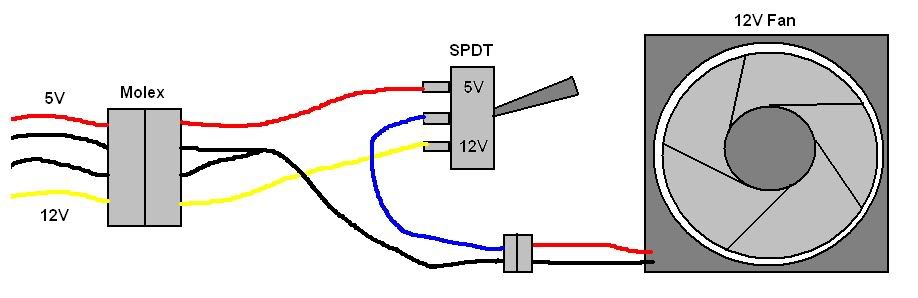
Here are a couple more diagrams for 12v/7v and 12v/8.7v, whichever you prefer:


  Send a message via Yahoo to BrianG Send a message via MSN to BrianG  
Reply With Quote
Old
  (#22)
BrianG
RC-Monster Admin
 
BrianG's Avatar
 
Offline
Posts: 14,609
Join Date: Nov 2005
Location: Des Moines, IA
01.12.2011, 10:33 PM

Quote:
Originally Posted by What's_nitro? View Post
That will run the fan at 12v or 5v. The 5v setting may be too low for a 12v fan to even start, and even if it does, airflow will be so little it will probably be all but useless. 7v is about the lowest I'd personally go...
  Send a message via Yahoo to BrianG Send a message via MSN to BrianG  
Reply With Quote
Old
  (#23)
What's_nitro?
Soldermaster Extraordinaire
 
What's_nitro?'s Avatar
 
Offline
Posts: 4,529
Join Date: Apr 2007
Location: Plymouth, MA, USA
01.12.2011, 10:35 PM

I was thinking about that- 5v might be too low to run the fan...
   
Reply With Quote
Old
  (#24)
BrianG
RC-Monster Admin
 
BrianG's Avatar
 
Offline
Posts: 14,609
Join Date: Nov 2005
Location: Des Moines, IA
01.12.2011, 10:35 PM

Quote:
Originally Posted by rawfuls View Post
Well I'm trying to setup a switch that would differentiate from 5V to 12V, and Off.. and such.

It's a wall of text because I'm electrically stupid...

--

EDIT:
Found a cool article while surfin' da webz.

http://www.silentpcreview.com/article6-page1.html

Pretty much talks about how to get 5V, 7V, or 12V through a switch, without using diodes..

Are there any cons to that version over Brians?
Thanks guys, and sorry for the excessive questions!
You can actually get 3.3v, 5v, 7v, 8.7, and 12v from a PC supply, but from experience, the 7v, 8.7v, and 12v are the usable voltages. The diodes are only needed if you want something different than those values.
  Send a message via Yahoo to BrianG Send a message via MSN to BrianG  
Reply With Quote
Old
  (#25)
rawfuls
roofles.
 
rawfuls's Avatar
 
Offline
Posts: 1,982
Join Date: Oct 2008
Location: Woodland Hills, CA
01.12.2011, 10:36 PM

I've seen numerous tests running fans @ 5V, 7V, and 12V.
SilentPCReview.com being on of them.

I'm sure it wouldn't matter if I used + or - for the wire that goes through the switch, right?
  Send a message via AIM to rawfuls Send a message via MSN to rawfuls  
Reply With Quote
Old
  (#26)
What's_nitro?
Soldermaster Extraordinaire
 
What's_nitro?'s Avatar
 
Offline
Posts: 4,529
Join Date: Apr 2007
Location: Plymouth, MA, USA
01.12.2011, 10:37 PM

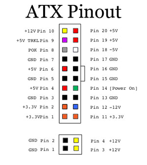
Just in case you're wondering where the 3.3v wire is...

   
Reply With Quote
Old
  (#27)
What's_nitro?
Soldermaster Extraordinaire
 
What's_nitro?'s Avatar
 
Offline
Posts: 4,529
Join Date: Apr 2007
Location: Plymouth, MA, USA
01.12.2011, 10:42 PM

Quote:
Originally Posted by rawfuls View Post
I'm sure it wouldn't matter if I used + or - for the wire that goes through the switch, right?
Aaaaacctualllyyy.......

It does. Either diagram would need to be hooked up exactly as pictured to work properly.
   
Reply With Quote
Old
  (#28)
BrianG
RC-Monster Admin
 
BrianG's Avatar
 
Offline
Posts: 14,609
Join Date: Nov 2005
Location: Des Moines, IA
01.12.2011, 10:44 PM

Quote:
Originally Posted by rawfuls View Post
I've seen numerous tests running fans @ 5V, 7V, and 12V.
SilentPCReview.com being on of them.

I'm sure it wouldn't matter if I used + or - for the wire that goes through the switch, right?
Well, 5v may work, but may not. You could temporarily wire the fan up to 5v and see if it starts reliably (may "grumble") and has the airflow you want before you make a more permanent switch setup.
  Send a message via Yahoo to BrianG Send a message via MSN to BrianG  
Reply With Quote
Old
  (#29)
BrianG
RC-Monster Admin
 
BrianG's Avatar
 
Offline
Posts: 14,609
Join Date: Nov 2005
Location: Des Moines, IA
01.12.2011, 10:44 PM

Quote:
Originally Posted by What's_nitro? View Post
Aaaaacctualllyyy.......

It does. Either diagram would need to be hooked up exactly as pictured to work properly.

That's correct!
  Send a message via Yahoo to BrianG Send a message via MSN to BrianG  
Reply With Quote
Old
  (#30)
What's_nitro?
Soldermaster Extraordinaire
 
What's_nitro?'s Avatar
 
Offline
Posts: 4,529
Join Date: Apr 2007
Location: Plymouth, MA, USA
01.12.2011, 11:04 PM

Quote:
Originally Posted by BrianG View Post
That's correct!
Where's my gold star sticker?
   
Reply With Quote
Reply


Currently Active Users Viewing This Thread: 1 (0 members and 1 guests)
 

Posting Rules
You may not post new threads
You may not post replies
You may not post attachments
You may not edit your posts

BB code is On
Smilies are On
[IMG] code is On
HTML code is On

Forum Jump


Powered by vBulletin® Version 3.8.11
Copyright ©2000 - 2025, vBulletin Solutions Inc.
vBulletin Skin developed by: vBStyles.com